Manual Kichler 84313PN Priam Lamp

Need a manual for your Kichler 84313PN Priam Lamp? Below you can view and download the PDF manual for free in English. This product currently has 7 frequently asked questions, 0 comments and has 0 votes. If this is not the manual you want, please contact us.

Is your product defective and the manual offers no solution? Go to a Repair Café for free repair services.

Manual

Loading…

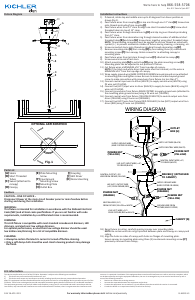
LIVE (HOT) WIRE (+DC)
FROM FIXTURE (RED or BLACK)
GROUND WIRE FROM
FIXTURE (BARE COPPER)
NEUTRAL WIRE (-DC)
FROM FIXTURE (YELLOW or WHITE)
LIVE (HOT) OUTPUT WIRE
(+DC) FROM DRIVER (RED)
NEUTRAL OUTPUT (-DC)
WIRE FROM DRIVER (YELLOW)
SUPPLY GROUND WIRE
(BARE COPPER OR GREEN)
NEUTRAL INPUT WIRE (-AC)
TO DRIVER (WHITE)
LIVE (HOT) INPUT WIRE (+AC)
TO DRIVER (BLACK)
SUPPLY GROUND WIRE
(BARE COPPER OR GREEN)
SUPPLY NEUTRAL WIRE (WHITE)
CANOPY [D]
DRIVER [J] (ATTACHED
TO CANOPY)
OUTLET
BOX [H]
P4 WIRE NUT
(YELLOW)
P3 WIRE NUT
(ORANGE)
WIRING DIAGRAM
P4 WIRE NUT
(YELLOW)
P3 WIRE NUT
(ORANGE)
P4 WIRE NUT
(YELLOW)
SUPPLY HOT WIRE (BLACK)
Fixture Diagram
Parts List
[A] Stems
[B] Short Threaded
Tubes
[C] Swivel (attached to
canopy)
[D] Canopy
[E] Plate Mounting
Screw
[F] Countersunk
Mounting Screw
[G] Mounting Plate
[H] Outlet Box
[I] Coupling
[J] LED Driver
[K] Decorative Ring
Cauons
CAUTION – RISK OF SHOCK –
Disconnect Power at the main circuit breaker panel or main fusebox before
starng and during the installaon.
WARNING:
This xture is intended for installaon in accordance with the Naonal Electrical
Code (NEC) and all local code specicaons. If you are not familiar with code
requirements, installaon by a cered electrician is recommended.
DIMMING:
This LED xture is compable with most standard incandescent dimmers, LED
dimmers, and electronic low voltage dimmers.
For opmal performance, an electronic low voltage dimmer should be used.
See kichler.com/dimming for a list of compable dimmers.
CLEANING:
• Always be certain that electric current is turned o before cleaning.
• Only a so damp cloth should be used. Harsh cleaning products may damage
the nish.
Installaon Instrucons
1) If desired, rotate top and middle arms up to 45 degrees from linear posion as
shown (Fig.1).
2) Pass xture wires from coupling[I] on top arm through one 12” stem[A]. Screw stem
onto threads protruding from coupling[I].
3) Pass xture wires from 12” stem through one short threaded tube[B]. Screw short
threaded tube into top of 12” stem.
4) Pass xture wires through decorave ring[K] and slip ring over threads protruding
from 12” stem.
5) Pass xture wires from decorave ring through desired number of addional short
threaded tubes[B] and stems[A]. Screw stems together using short threaded tubes.
NOTE: Thread locking compound must be applied to all stem threads as noted with
symbol (4) to prevent accidental rotaon of xture during cleaning, re-lamping, etc.
6) Screw connected stems onto threads protruding through decorave ring[K].
7) Remove mounng plate[G] from canopy[D] by unscrewing three (3) countersunk
mounng screws[F] from canopy. Retain screws for re-aaching canopy to
mounng plate.
8) Pass xture wires from last stem through swivel[C] aached to canopy[D].
9) Screw swivel into end of last stem.
10) Aach mounng plate[G] to outlet box[H] using the plate mounng screws[E].
Mounng plate can be adjusted to suit posion of xture.
11) Cut xture wires a MINIMUM of 6” from top edge of canopy.
NOTE: If the black and white driver lead wires must be trimmed, cut the wires a
MINIMUM of 6” from the top edge of canopy.
12) Wrap supply ground wire (BARE COPPER OR GREEN) around ground screw aached
to mounng plate and ghten screw. Be sure to leave extra wire beyond ground
screw to make connecon with ground wire from xture (no less than 2”).
13) Connect neutral input wire to driver (WHITE) to supply neutral wire (WHITE) using
P4 wire nut (YELLOW).
14) Connect live (HOT) input wire to driver (BLACK) to supply hot wire (BLACK) using P4
wire nut (YELLOW).
15) Connect ground wire from xture (BARE COPPER) to supply ground wire (aached to
the mounng plate ground screw) using a P4 wire nut (YELLOW).
16) Connect neutral wire from xture (YELLOW OR WHITE) to neutral output wire from
driver (YELLOW) using P3 wire nut (ORANGE).
17) Connect live (HOT) wire from xture (RED OR BLACK) to live (HOT) output wire from
driver (RED) using P3 wire nut (ORANGE).
For warranty informaon please visit: kichler.com/warranty
This device complies with part 15 of the FCC Rules. Operaon is subject to the following two condions:
1) This device may not cause harmful interference, and
2) This device must accept any interference received, including interference that may cause undesired operaon.
Note: This equipment has been tested and found to comply with the limits for a Class B digital device, pursuant to part 15 of the
FCC Rules. These limits are designed to provide reasonable protecon against harmful interference in a residenal installaon.
This equipment generates, uses and can radiate radio frequency energy and, if not installed and used in accordance with the
instrucons, may cause harmful interference to radio communicaons. However, there is no guarantee that interference will
not occur in a parcular installaon. If this equipment does cause harmful interference to radio or television recepon, which
can be determined by turning the equipment o and on, the user is encouraged to try to correct the interference by one or
more of the following measures:
Reorient or relocate the receiving antenna.
Increase the separaon between the equipment and receiver.
Connect the equipment into an outlet on a circuit dierent from that to which the receiver is connected.
Consult the dealer or an experienced radio/TV technician for help.
FCC Informaon:
REV 28-APR-2021 IS-84313-US
We’re here to help 866-558-5706
Hrs: M-F 9am to 5pm EST
18) Raise xture to ceiling, carefully passing canopy over mounng plate.
NOTE: Be certain wires do not get pinched between plate and canopy or canopy and
ceiling.
19) Align the holes on sides of canopy with holes on anges of mounng plate.
Secure canopy to mounng plate using three (3) countersunk mounng screws[F]
previously removed from canopy.
A
B
H
E
G
J
F
C
D
I
K
A
B
OPTIONAL ARM ROTATION :
84313
Fig. 1
OPTIONAL ARM ROTATION
A
B
H
E
G
J
F
C
D
I
K
A
B
OPTIONAL ARM ROTATION :
84313
Download manual in English (PDF, 0.43 MB)
(Consider the environment and only print this manual if it is really necessary)

Loading…

Rating

Let us know what you think about the Kichler 84313PN Priam Lamp by leaving a product rating. Want to share your experiences with this product or ask a question? Please leave a comment at the bottom of the page.
Are you satisfied with the Kichler 84313PN Priam Lamp?
Yes No
Be the first to rate this product
0 votes

Join the conversation about this product

Here you can share what you think about the Kichler 84313PN Priam Lamp. If you have a question, first carefully read the manual. Requesting a manual can be done by using our contact form.

More about this manual

We understand that it’s nice to have a paper manual for your Kichler 84313PN Priam Lamp. You can always download the manual from our website and print it yourself. If you would like to have an original manual, we recommend you contact Kichler. They might be able to provide an original manual. Are you looking for the manual of your Kichler 84313PN Priam Lamp in a different language? Choose your preferred language on our homepage and search for the model number to see if we have it available.

Specifications

Brand Kichler
Model 84313PN Priam
Category Lamps
File type PDF
File size 0.43 MB

All manuals for Kichler Lamps
More manuals of Lamps

Frequently Asked Questions about Kichler 84313PN Priam Lamp

Our support team searches for useful product information and answers to frequently asked questions. If you find an inaccuracy in our frequently asked questions, please let us know by using our contact form.

Is all LED lighting dimmable? Verified

No, not all LED lights are dimmable. This is indicated on the packaging or the light itself.

This was helpful (462) Read more

I put a new light in my lamp but it won't turn on, why is that? Verified

Some lamps are made for light sources of a specific wattage. When a light source is inserted that requires a higher wattage than the lamp can provide, the light may not turn on. If the lamp delivers a much higher wattage than what the light source is made for, the light source can burn out.

This was helpful (315) Read more

Why is the colour of light important? Verified

There generally are two kinds of light, warm light and cold light. Cold light keeps you sharp and awake. Warm light has a relaxing effect. The warmth of the light is measured in Kelvin and is indicated on the packaging of the lamp itself.

This was helpful (255) Read more

What is lumen? Verified

Lumen is a measuring unit for the total amount of visible light emitted by a source.

This was helpful (190) Read more

What screw bases exist? Verified

Worldwide there many types of sockets, but most used are those based on the Edison screw, indicated with the letter E. In most countries screw bases E27 and E14 are standard. In the United States E26, E17, E12 and E10 are standard.

This was helpful (142) Read more

What do watts say about my lamp? Verified

Watt is a measuring unit for electricity consumption. Lamps that produce more light, generally use more Watt, but for comparing light output you should always use lumen.

This was helpful (113) Read more

What is LED? Verified

LED stands for Light-Emitting Diode. By running power through a semiconductor in the right direction, light is emitted.

This was helpful (98) Read more
Manual Kichler 84313PN Priam Lamp