
INSTALLATION INSTRUCTIONS
INSTRUCCIONES DE INSTALACIÓN/ INSTRUCTIONS D’INSTALLATION
For Models:
Para los Modelos:
Pour les Modèles:
Here are the
tools you’ll
need to
complete your
installation:
Estas son las
herramientas
que usted
necesitará para
completar su
instalación:
Voici les outils
dont vous
aurez besoin
pour réaliser
l’installation:
Ladder
Escalera
Échelle
Pliers
Alicates
Pince
Wire Strippers
Pelacables
Pince à dénuder
READ AND SAVE THESE INSTRUCTIONS
These instructions are provided for your safety. It
is very important that they are read carefully and
completely before beginning installation of the
lighting xture.
LEA Y GUARDE ESTAS INSTRUCCIONES
Estas instrucciones se proporcionan para su
seguridad. Es muy importante leerlas detenid-
amente y completamente antes de comenzar la
instalación de la lámpara.
LISEZ ET CONSERVEZ CES INSTRUCTIONS
Ces instructions sont fournies pour votre sécurité.
Il est très important de les lire attentivement dans
leur intégralité avant d’entreprendre l’installation
du luminaire.
Fixture weight ±2 lbs:
Peso ±2 lb:
Poids xe ±2 lbs:
•
• All wiring must be in accordance with national
and local electrical codes ANSI/NFPA 70. If you
are unfamiliar with wiring or in doubt, consult a
qualied electrician.
• To avoid possible electrical shock, before
installing your light xture, disconnect the power
by turning off the circuit breakers to the outlet box
associated with the wall switch location.
• The lighting xture must be grounded. If the
ground wire for the installation site is not present,
immediately STOP installation and consult a
qualied electrician.
• Todo el cableado debe realizarse de acuerdo con
los códigos eléctricos locales y nacionales ANSI/
NFPA 70. Si no está familiarizado con el cableado,
o si tiene duda, consulte a un electricista calicado.
• Para evitar una posible descarga eléctrica, antes
de instalar su lámpara, desconecte la energía
apagando los interruptores automáticos (breakers)
que alimentan la caja de salida asociada con la
ubicación del interruptor de pared.
•
• L’appareil d’éclairage doit être mis à la terre.
Si le l de terre du lieu d’installation n’est pas
présent, ARRÊTEZ immédiatement l’installation et
consultez un électricien qualié.
•
•
Tout le câblage doit être conforme aux codes
électriques nationaux et locaux en vigueur et à la
norme ANSI/NFPA70. Si vous n'avez pas l'habitude
de faire ce câblage ou en cas de doute, adressez-
vous à un électricien qualié.
• Pour éviter tout choc électrique, avant d’installer
le luminaire, coupez le courant en éteignant les
disjoncteurs de la boîte électrique associée à
l’interrupteur mural.
•
Le luminaire doit être mis à la terre. Si le l
de terre du lieu d’installation n’est pas présent,
ARRÊTER immédiatement l’installation et
consulter un électricien qualié.
Part #/Pieza #/Pièce #
Hardware Service Kit/Kit De Mantenimiento Del Equipo/Trousse De
Maintenance Quincaillerie
Finish/Finish/FiniModel/Modelo/Modèle
Glass/Domo De Vidrio/Verre
Type/Tipo/Type
©2021 Hunter Fan Co.
Light Pendant
Luz Colgante
Lumière Chaînette
Part #/Pieza #/Pièce # Model/Modelo/ Modèle
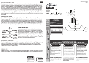
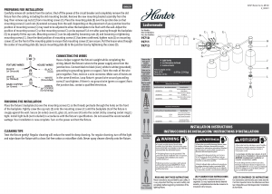
ENGLISH
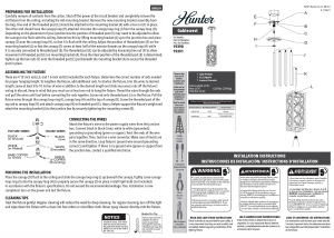
In order to use a 12in rod by
itself you must rst remove
the post from the 6in rod and
install it on one of the ends of
the 12in rod.
Screwdriver
Destornilladore
Tournevis
Twist or tape wire ends
together to make it
easier to pass them
through the downrods.
Threaded post may also
be removed for easier
wire access.
Hunter Pro Tip:
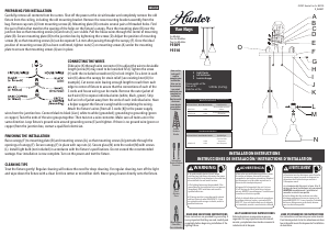
J
I
K
N
M
L
A
D
G
H
B
C
E
F
19072
19215
19216
19217
Bluff View
KD83801214
Brushed Nickel/Níquel Pulido/
Nickel Brossé
19072 19215
19216 19217
KD51901147
Clear Halophane Glass/Vidrio
Transparente Tipo Holophane/
Verre Holophane Transparent
19072 19215
19216 19217
ML118
R_071321
12.15 lbs (5.51 kg)
1
1
1
FINISHING THE INSTALLATION
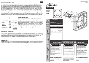
CONNECTING THE WIRES
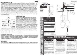
ASSEMBLING THE FIXTURE
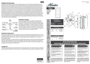
PREPARING FOR INSTALLATION
CLEANING TIPS
Treat the xture gently! Regular cleaning will reduce the need for deep
cleaning. For regular cleaning, turn off the light and wipe down the
xture with a clean lint-free cotton or microber cloth. Never spray
cleaner directly onto the xture.
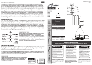
Carefully remove all contents from the carton. Shut off the power at the circuit breaker and completely remove the
old xture from the ceiling, including the old mounting bracket. Remove the new mounting bracket assembly from
the bag. One end of the threaded post (H) should be attached to the mounting bracket (A) with a hex nut (G) in place.
The other end should have the canopy loop (E) attached. Unscrew the canopy loop ring (F) from the canopy loop (E).
Depending on the placement of your junction box the position of threaded post (H) may need to be adjusted to allow
the canopy to be ush with the ceiling. Determine this by lifting mounting bracket (A) up to the junction box and
place canopy (D) over the canopy loop (E), so that it is ush with the ceiling. Adjust the position of threaded post (H)
on the mounting bracket (A) so that the canopy (D) covers at least half of the exterior threads on the canopy loop (E)
while it is securely connected to threaded post (H). The threaded post (H) can be adjusted by loosening hex nut (G)
to allow movement of threaded post (H) on mounting bracket (A). Once the ideal position of the threaded post (H) is
determined, tighten up the hex nut (G) onto the threaded post (H) just beneath the mounting bracket (A) to secure the
threaded post in place.
There are 4 12-inch rods (I), and 1 6-inch rod (J) included for each xture. Determine the correct number of rods needed
for proper hanging height. To lengthen the xture, add additional rods. To shorten the xture, trim the wires to desired
length. Leave at least 8 to 10 inches of wire in addition to the desired length and slide any excess rods off the xture’s
wiring to discard. Keep in mind that you must use at least one rod to hang the xture. Thread the wires through the
rods and pull the wires until taut before connecting the rods together. Screw rod onto threaded post (K) on the xture.
Pull the xture wires through the canopy loop ring (F), the top of canopy (D), and canopy loop (E). Screw the threaded
post of the top rod to canopy loop (E). Have a helper support the xture’s weight and attach the mounting bracket (A) to
the junction box by securely tightening the mounting screws (B).
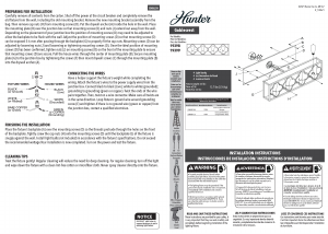
Attach the xture’s wires to the power supply wires from the junction
box. Connect black to black (Live); white to white (grounded);
grounding to grounding (green or copper). Twist the ends of the wire
pairs together. Then, twist on a wire connector. Make sure all twists are
in the same direction. Loop xture’s ground wire around grounding
screw (C) and tighten. If there is no ground wire (green or copper) from
the junction box, contact a qualied electrician.
Place the canopy (D) ush to the ceiling and slide the canopy loop ring (F) up beneath the canopy. Tightly screw canopy
loop ring (F) onto the canopy loop (E) to properly secure the canopy (D) in place. Install light bulb (not included) in
accordance with the xture’s specications. Do not exceed the recommended wattage.
Set glass (O) in ring (N) with the rounded side down and secure glass with the bendable tabs on the inside of the ring.
Then align the holes of the glass ring (N) with the holes of metal shade (M) and secure them with the cap nuts (L). Your
installation is now completed. Turn on the power and test the xture.

Join the conversation about this product
Here you can share what you think about the Hunter 19215 Bluff View Lamp. If you have a question, first carefully read the manual. Requesting a manual can be done by using our contact form.