• Avoid prolonged contact with dust from power sanding, sawing, grinding, drilling,
and other construction activities. Wear protective clothing and wash exposed areas
with soap and water. Allowing dust to get into your mouth, eyes, or lay on the skin may
promote absorption of harmful chemicals.
WARNING: Use of this tool can generate and/or disburse dust, which may cause serious
and permanent respiratory or other injury. Always use NIOSH/OSHA approved respiratory pro-
tection appropriate for the dust exposure. Direct particles away from face and body.
CAUTION: Wear appropriate personal hearing protection during use. Under some
conditions and duration of use, noise from this product may contribute to hearing loss.
• The label on your tool may include the following symbols. The symbols and their definitions
are as follows:
V ......................volts A........................amperes
Hz ....................hertz W ......................watts
min....................minutes ....................alternating current
..................direct current
n
o......................no load speed
....................Class II Construction …/min ..............revolutions per minute
....................earthing terminal ....................safety alert symbol
SAVE THESE INSTRUCTIONS
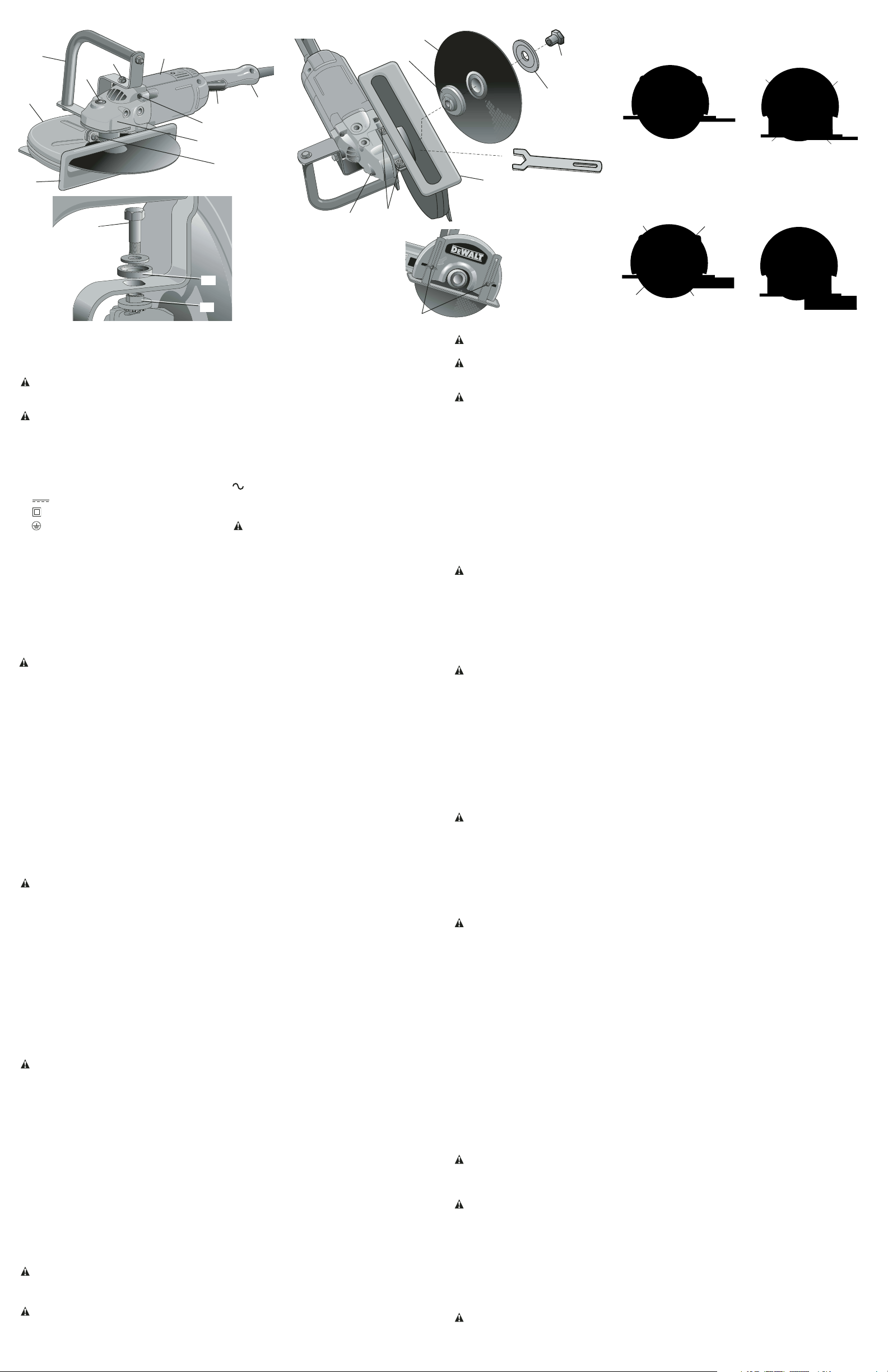
COMPONENTS
Refer to Figure 1 for a complete list of components.
ASSEMBLY
Rotating the Gear Case (Figures 2, 3)
NOTE: This machine is assembled at the factory with the spindle on right side of the unit for
right handed operation.
CONVERSION FROM RIGHT HANDED TO LEFT HANDED
CAUTION: Turn off and unplug the tool before making any adjustments or remov-
ing or installing attachments or accessories. Be sure the trigger switch is in the OFF
position.
1. Place unit on a firm, flat work surface.
2. Remove bail handle (F) by removing 2 hex bolts (Q), the top insulators (R) and the bottom
insulators (S).
3. Remove guard by removing guard mounting nuts (N).
4. Remove the 4 gear case mounting screws (O).
5. Rotate gear case 180˚ without pulling gear case (P) away from the body of the tool.
NOTE: If the gear case and motor housing become separated by more than 1/8", the tool
must be serviced and re-assembled by a D
EWALT service center. Failure to have the tool
serviced may cause brush, motor and bearing failure.
6. Replace the 4 gear case mounting screws (O) and tighten firmly to 30 in-lbs.
7. Reattach the guard so the shoe faces in the same direction as the trigger switch handle
(H). Be sure the guard is on the spindle bearing hub as far as it will go and both guard tabs
engage the slot in the spindle bearing hub. Tighten guard mounting nuts (N) securely to
50 in-lbs.
8. Replace the bail handle with the bottom insulators (S), top insulators (R) and the 2 hex bolts
(Q) then tighten securely to 75 in-lbs. Refer to Figure 2 for orientation of the bail handle.
WARNING: Plastic insulators must be assembled to hex bolts and bracket as shown in
Figure 3. Failure to do so may result in electric shock injury.
OPERATION
Motor
Be sure your power supply agrees with the nameplate marking. Voltage decrease of more
than 10% will cause loss of power and overheating. All D
EWALT tools are factory tested; if
this tool does not operate, check the power supply.
Spindle Lock Button (Figure 4)
The spindle lock button (I) is used to lock the spindle when changing accessories. To engage
the spindle lock button, disconnect the tool from the power supply and be sure switch is in
OFF position. Depress the lock button and turn the wheel and spindle until the lock button
engages the spindle. Use supplied wrench to unscrew the spindle nut (J) and remove or mount
accessories. Spindle threads are right hand.
Installing Abrasive Wheels (Figures 4, 5)
CAUTION: Turn off and unplug the tool before making any adjustments or remov-
ing or installing attachments or accessories. Be sure the trigger switch is in the OFF
position.
1. Lay unit on a firm surface with bottom of shoe (E) facing up.
2. Loosen depth adjustment wing nuts (C), move shoe to allow easiest access to spindle
nut, then tighten wing nuts to hold shoe in place.
3. Using supplied 1-1/8" (28mm) open end wrench, remove spindle nut (J), outer clamp
washer (K) and used wheel (L) if one is installed. Hold spindle from turning with spindle
lock button. Spindle threads are right hand.
4. Make sure inner clamp washer (M) is in place and ears are engaged with spindle flats.
Slip wheel through bottom of shoe and slip wheel over spindle. Be sure wheel goes over
pilot diameter of inner clamp washer. Slip on outer clamp washer. Start threading on spin-
dle nut which will self align outer clamp washer.
5. Engage spindle lock button and tighten nut with wrench. Do not over tighten spindle
nut.
6. Turn wheel by hand to ensure it is properly centered. The wheel should not hit the shoe,
guard or nut. The nut and flanges should be tight.
7. Be sure to readjust shoe for proper depth of cut.
CAUTION: Only use 12" Type 1 wheels with 1" arbor hole with this tool. Never force a
wheel onto the machine or alter the size of the arbor hole.
Depth of Cut (Figures 6, 7)
WARNING: Edge cutting can be performed only with wheels that are designed and speci-
fied for this purpose. Protect yourself during edge cutting by directing the open side of the
guard toward a surface.
WARNING: Wheels used for cutting may break or kick back if they bend or twist while the
tool is being used to do cut-off work.
WARNING: Do not use edge cutting wheels for surface grinding applications because
these wheels are not designed for side pressures encountered with surface grinding. Wheel
breakage and injury may result.
CAUTION: Turn off and unplug the tool before making any adjustments or remov-
ing or installing attachments or accessories. Be sure the trigger switch is in the OFF
position.
The depth of cut can be adjusted by loosening the two depth adjustment wing nuts (C) on the
outside of the guard to change the position of the shoe. Using the slot in the wrench (provided)
securely tighten the wing nuts.
TO CUT METALS AND THIN MATERIALS
When cutting metals and other thin materials, adjust shoe for maximum depth of cut as shown
in Figure 6.
TO CUT STONE OR MASONRY MATERIALS
Set the wheel exposure to about 1/2" (13mm) beyond the shoe. For many applications, the
material will readily break along the 1/2" (13mm) deep scored line. If a deeper cut is needed,
increase the depth of cut in approximately 1/2" (13mm) increments between cuts (Figure 7).
To Operate (Figure 2)
CAUTION: Before attempting to start, grasp tool firmly with both hands before lifting.
1. Grasp trigger switch handle (H) and bail handle (F) firmly.
2. Line up wheel with material to be cut. Be sure nothing is near or in line with the wheel.
3. Depress and hold trigger switch (A) then slowly feed wheel into work with firm pressure.
Keep the shoe (E) firmly and squarely against the work. Do not force the tool. For maximum
efficiency and wheel life, keep the wheel speed high.
4. To stop tool, release trigger switch (A).
Applications
WARNING: NEVER cut magnesium with this tool. Magnesium particles may ignite causing
personal injury.
• 1/8" (3mm) max. gauge sheet metal
• Concrete, cinder blocks and bricks
• Reinforcing rod; generally under 3/4" (19mm) diameter
• 1/8" (3mm) diameter concrete wire mesh
• Corrugated floor and ceiling form (concrete forms)
• Electrical conduit 1/8" (3mm) wall thickness
• 1/8" (3mm) max. thick structural forms such as channel, angles, plate, etc.
NOTE: The cutting of materials heavier than those listed above are not recommended due to
the possibility of electrical overloading.
TO ADJUST ANGLE OF GUARD
CAUTION: Turn off and unplug the tool before making any adjustments or remov-
ing or installing attachments or accessories. Be sure the trigger switch is in the OFF
position.
1. Loosen the guard mounting nuts (N), shown in Figure 2.
2. Grasp the guard firmly and rotate to desired angle.
3. Tighten clamp nuts to lock guard in position.
MAINTENANCE
Motor Brushes
CAUTION: Turn off and unplug the tool before making any adjustments or remov-
ing or installing attachments or accessories. Be sure the trigger switch is in the OFF
position.
When brushes become worn, the tool will automatically stop, preventing damage to the motor.
Brush replacement should be performed by D
EWALT authorized service centers or other qual-
ified service personnel. Qualified service personnel should follow the procedures below when
replacing motor brushes.
1. Remove the brush doors located on the sides of motor housing.
2. To remove the brush, hold the female terminal, which is attached to the brush lead wire,
and disconnect the female terminal from the male terminal.
3. Pull the brush straight up out of the brush holder.
4. Before new brushes can be installed, the brush spring arm must be pulled back out of the
way.
5. Replace brushes, in pairs, with original D
EWALT brushes available from DEWALT author-
ized service centers.
6. Ensure that the brushes slide freely in brush box.
7. Reconnect the brush lead wire to brush box terminal.
8. Re-install the brush doors before using the tool. Torque screws to 10 in./lbs. maximum.
Overtightening may cause screws to strip.
Cleaning
WARNING: Blowing dust and grit out of the motor housing using clean, dry compressed air
is a necessary regular maintenance procedure. Dust and grit containing metal particles often
accumulate on interior surfaces and could create an electrical shock or electrocution if not fre-
quently cleaned out. ALWAYS WEAR SAFETY GLASSES.
CAUTION: Never use solvents or other harsh chemicals for cleaning the non-metallic parts
of the tool. Use a clean, dry cloth only.
Lubrication
DEWALT tools are properly lubricated at the factory and are ready for use.
Accessories
Recommended accessories (abrasive masonry cutting, abrasive asphalt cutting, abrasive
metal cutting and diamond blades) for use with your tool are available at extra cost from your
local dealer or authorized service center. If you need assistance in locating any accessory for
your tool, contact: D
EWALT Industrial Tool Co., 701 East Joppa Road, Baltimore, MD 21286.
WARNING: Accessories must be rated for at least the speed recommended on the
tool warning label. Wheels and other accessories running over rated speed can fly apart and
cause injury. Accessory ratings must always be above tool speed as shown on tool nameplate.
FIG. 4
J
L
K
M
I
N
FIG. 5
E
C
FIG. 6
YES / OUI / SÍ
NO / NON / NO
FIG. 7
NO / NON / NO
YES / OUI / SÍ
FIG. 2
F
G
I
N
O
D
E
H
A
P
Q
FIG. 3
S
Q
R
METALS OR THIN MATERIAL
MÉTAUX OU MATÉRIAUX MINCES
METALES O MATERIAL FINO
MASONRY MATERIAL
PRODUIT DE MAÇONNERIE
MATERIAL DE MAMPOSTERÍA


Join the conversation about this product
Here you can share what you think about the DeWalt D28754 Circular Saw. If you have a question, first carefully read the manual. Requesting a manual can be done by using our contact form.