D. ELECTRICAL CONNECTIONS
1. Switch Box
On the left hand side of the frame, between the upper
and lower wheel covers, are two loosely fitted screws.
These are the mountings for the switch box.
Remove the screws and attach the switch box, with
the safety bar on the wheel cover sitting snugly against
the safety switch.
The safety switch operates when the wheel cover is
opened. The safety bar, mounted on the wheel cover,
pushes the switch into the OFF position, thereby
preventing the machine from operating.
You will notice that the Safety Bar and Switch Box
have elongated mounting holes. These allow the
assembly to be adjusted so that the switch operates
immediately the door is opened.
2. The Motor
Two cables extend from the switch box. One cable
carries a 13 amp BS 1360 plug, the other, shorter
cable is now connected to the motor, as follows:
2.1 Remove the motor connector box cover plate.
2.2 Remove the gland securing nut from the end
of the cable, (leaving the gland ON the cable),
and thread the cable through the hole in the motor
connector box. Replace the gland securing nut
on the cable, once the cable is through the hole,
and secure it, loosely for the time being, so that
the cable is not held.
2.3 Connect the YELLOW/GREEN wire to the
EARTH terminal, which is attached to the
casing.
2.4 The other two wires are connected to the other
two terminals on the terminal block.
2.5 Ensuring all wires are firmly secured, pull any
excessive cable that may be inside the box, back
out through the cable inlet. Ensure there is a little
slack in the cable and the wires are NOT taught,
before tightening the gland securing nut and
replacing the connector box cover.
2.6 Attach the cable, (between the switch box and
motor), to the main frame, with the cable clips
provided.
Your Band Saw is now fully assembled, but
before use, it is MOST IMPORTANT that the
following adjustments are made. It is equally
important that these adjustments are
constantly checked and maintained.
The sequence of adjustment is as follows:
1. Apply tension to the blade by screwing the tension
adjuster knob clockwise until the blade feels firm
on its’ run between the two wheels.
2. Turn the upper wheel clockwise, by hand, and
observe the reaction of the blade, and its position
on the tyre of the upper wheel
3. If the blade begins to move towards the front edge
of the tyre, (i.e. towards you as you look at it),
slowly turn the alignment screw anticlockwise,
causing the upper wheel to tilt outwards at the top,
thereby causing the blade to move further towards
the back edge of the tyre. Conversly, if the blade
tends to run towards the back edge of the tyre,
turn the alignment knob clockwise, moving the
upper wheel inwards at the top, thereby causing
the blade tomove towards the front edge of the
tyre.
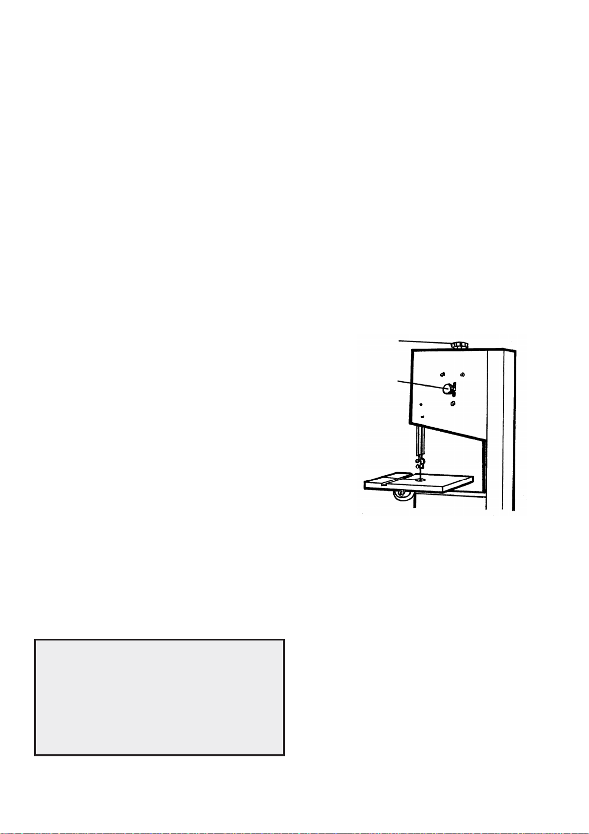
Blade
Tension
Adj. Knob
Wheel
Alignment
Knob
Fig. 8
ADJUSTMENTS
A.BLADE ALIGNMENT AND TENSION
Blade tension is effected by raising or lowering the
upper wheel, by means of the Blade Tension Adjuster
Knob (A, fig. 1) The upper wheel is mounted on a
spring loaded trunnion, and tension is therefore a
matter of ‘feel’.
Additionally, the upper wheel can be adjusted so that
it is correctly aligned with the lower wheel, and to
ensure the blade will run centrally about both wheels.
This adjustment is effected by turning the Alignment
Knob, shown in fig. 8.
Screwing the knob ‘in’ (clockwise), will cause the upper
wheel to tilt inwards at the top slightly, which in turn
causes the blade to run on the outside of the wheel.
Screwing the Knob anticlockwise, has the opposite
effect.
The Upper wheel carries a rubber tyre which has a
convex outer surface. It is important therefore to
ensure the blade runs exactly in the centre of the tyre.
8


Join the conversation about this product
Here you can share what you think about the Clarke CBS14WC Bandsaw. If you have a question, first carefully read the manual. Requesting a manual can be done by using our contact form.