
Sony Corporation 2000 Printed in Japan
XM-423SL
3-043-303-11 (1)
Stereo Power
Amplifier
Operating Instructions
Mode d’emploi
Installation
Before Installation
•Choose the mounting location carefully so that
the unit will not interfere with the normal
movements of the driver, and so it will not be
exposed to direct sunlight or hot air from the
heater.
•Do not install the unit under the floor carpet,
where the heat dissipation from the unit will
be considerably impaired.
First, place the unit where you plan to install it,
and mark the positions of the four screw holes
on the surface of the mounting board (not
supplied). Then drill the holes approximately
3 millimeters (mm) in diameter and mount the
unit onto the board with the supplied mounting
screws. The supplied mounting screws are
14 mm long. Therefore, make sure that the
mounting board is thicker than 9 mm.
Installation
Avant l’installation
•Choisissez un endroit de montage judicieux
pour que l’appareil ne gêne pas les
mouvements normaux du conducteur et pour
qu’il ne soit pas exposé aux rayons directs du
soleil ou à proximité d’une bouche d’air
chaud du système de chauffage.
•N’installez pas l’appareil sous le tapis, car cela
empêcherait la dissipation de chaleur de
l’appareil.
Tout d’abord, mettez l’appareil où vous
prévoyez de l’installer et tracez les quatre trous
de vis sur la surface de la plaque de montage
(non fournie). Forez ensuite les trous selon un
diamètre d’environ 3 millimètres (mm) et
installez l’appareil sur la plaque avec les vis de
montage fournies. Les vis de montage fournies
font 14 mm de long. Par conséquent, assurez-
vous que la plaque de montage fait plus de
9 mm d’épaisseur.
Specifications
Circuit system B.T.L. output circuits
Speaker impedance 4 – 8 Ω (stereo)
Maximum outputs 55 W × 4 (at 4 Ω, 16 V)
Rated outputs (supply voltage at 14.4 V,
20 Hz – 20 kHz) 19 W × 4 (1 % THD, at 4 Ω)
23 W × 4 (10 % THD, at 4 Ω,
1 kHz)
Frequency response
20 Hz – 50 kHz ( dB)
Harmonic distortion
0.05 % or less (at 1 kHz)
Input level adjustment range
2 – 8 V
Current Drain 9.0 A (at rated power)
Input impedance 34 Ω
High-pass filter FLAT/100/120/150 Hz
Dimensions Approx. 200 × 35 × 111.8 mm
(w/h/d) not incl.
projecting parts and
controls
Mass Approx. 0.7 kg not incl.
accessories
Supplied accessories
Power connecting cord (1)
Mounting screws (4)
Design and specifications are subject to change
without notice.
Features
•This unit is a booster amplifier for use with an ISO connector only.
•Maximum power output of 55 watts per channel (at 4 Ω).
•Built in selectable HPF (High-pass filter).
•Easy connection (Simple installation with a supplied connecting cord).
•Power amplifier with separated L ch, R ch power supply.
Spécifications
Circuiterie Circuits de sortie B.T.L.
Impédance des haut-parleurs
4 – 8 Ω (stéréo)
Sorties maximales 55 W × 4 (à 4 Ω, 16 V)
Sorties nominales (tension d’alimentation à
14,4 V, 20 Hz – 20 kHz)
19 W × 4 (1 % THD, à 4 Ω)
23 W × 4 (10 % THD, à 4 Ω,
1 kHz)
Réponse en fréquence
20 Hz – 50 kHz ( dB)
Distorsion harmonique
0,05 % ou inférieure
(à 1 kHz)
Plage de réglage du niveau d’entrée
2 – 8 V
Consommation de courant
9,0 A (à la puissance
nominale)
Impédance d’entrée
34 Ω
Filtre passe-haut FLAT/100/120/150 Hz
Dimensions Approx. 200 × 35 × 111,8 mm
(l/h/p) parties et
commandes saillantes non-
comprises
Poids Approx. 0,7 kg sans les
accessoires
Accessoires fournis
Câble d’alimentation (1)
Vis de montage (4)
La conception et les spécifications sont sujettes
à modifications sans préavis.
Caractéristiques
•Cet appareil est un amplificateur de puissance uniquement destiné à être raccordé via un connecteur
ISO.
•Puissance de sortie maximale de 55 watts par canal (à 4 Ω).
•HPF (filtre passe-haut) variable intégré.
•Simplicité de connexion (simple installation avec un câble d’alimentation).
•Amplificateur de puissance à alimentation séparée pour les canaux L et R.
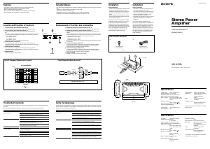
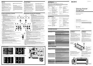
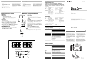
Location and Function of Controls
1 Cut-off frequency select switch/Front (See Fig. 1)
Sets the cut-off frequency (100/120/150 Hz) for the high-pass filter.
2 Cut-off frequency select switch/Rear (See Fig. 1)
Sets the cut-off frequency (100/120/150 Hz) for the high-pass filter.
Tip
For the best effect, use a high-pass filter when you connect a subwoofer. The cut-
off frequency changes depending on the diameter of the speakers connected to
the main amplifier as follows:
16 cm speaker – 100 Hz
13 cm speaker – 120 Hz
10 cm speaker – 150 Hz
Refer also to the manual of the subwoofer you are using.
3 LEVEL adjustment control/Front
The input level can be adjusted with this control when using source
equipment made by other manufacturers. Turn it to MAX when the output
level of the car audio seems low.
4 LEVEL adjustment control/Rear
The input level can be adjusted with this control when using source
equipment made by other manufacturers. Turn it to MAX when the output
level of the car audio seems low.
5 POWER indicator
Lights up in green during operation.
Emplacement et fonction des commandes
1 Sélecteur de fréquence de coupure/Avant (Voir Fig. 1)
Règle la fréquence de coupure (100/120/150 Hz) pour le filtre passe-haut.
2 Sélecteur de fréquence de coupure/Arrière (Voir Fig. 1)
Règle la fréquence de coupure (100/120/150 Hz) pour le filtre passe-haut.
Conseil
Pour obtenir le meilleur effet, utilisez un filtre passe-haut si vous raccordez un haut-
parleur d’extrêmes-graves. La fréquence de coupure change comme suit en fonction
du diamètre des haut-parleurs connectés à l’amplificateur principal :
Haut-parleur de 16 cm – 100 Hz
Haut-parleur de 13 cm – 120 Hz
Haut-parleur de 10 cm – 150 Hz
Reportez-vous également au mode d’emploi du haut-parleur d’extrêmes-graves que
vous employez.
3 Commande de réglage LEVEL/Avant
Le niveau d’entrée peut se régler avec cette commande lors de l’utilisation
d’équipements source d’autres fabricants. Mettez-le sur MAX lorsque le
niveau de sortie de l’installation audio paraît faible.
4 Commande de réglage LEVEL/Arrière
Le niveau d’entrée peut se régler avec cette commande lors de l’utilisation
d’équipements source d’autres fabricants. Mettez-le sur MAX lorsque le
niveau de sortie de l’installation audio paraît faible.
5 Indicateur POWER
S’allume en vert en cours de fonctionnement.
FRONT
LEVEL
HP-FILTER
FLAT
100Hz
MIN MAX
150Hz
120Hz
FLAT
100Hz
150Hz
120Hz
REAR
LEVEL
HP-FILTER
MIN MAX
POWER
Problem
The POWER indicator
does not light up.
Alternator noise is heard.
The sound is too low.
No sound is heard.
Guide de dépannage
La liste suivante vous permettra de remédier à la plupart des problèmes que vous pourriez rencontrer
dans le cadre de l’utilisation de votre appareil. Avant de passer en revue la liste ci-dessous, vérifiez les
procédures de raccordement et d’utilisation.
Problème
L’indicateur POWER ne
s’allume pas.
L’alternateur émet un bruit.
Le son est trop faible.
Aucun son n’est audible.
Cause/Solution
Le fusible est grillé. t Remplacez le fusible par un neuf.
Le fil de masse n’est pas connecté correctement.
t Fixez correctement le fil de masse à un point métallique de la voiture.
L’appareil maître connecté n’est pas allumé.
t Mettez l’appareil maître sous tension.
Vérifiez la tension de la batterie (10,5 V ou inférieure).
Le fil de masse n’est pas connecté.
t Fixez le fil de masse à un point métallique de la voiture.
Le fil de masse n’est pas connecté correctement.
t Fixez correctement le fil de masse à un point métallique de la voiture.
Les fils négatifs des haut-parleurs touchent la carrosserie de la voiture.
t Eloignez les fils de la carrosserie de la voiture.
La commande de réglage LEVEL est mise en position “MIN”.
Un ou plusieurs commutateurs doivent être réglés entre deux positions de
réglage (c.-à-d., mal réglés); réglez correctement les commutateurs.
Vérifiez la tension de la batterie (18 V ou plus).
Le câble de haut-parleur est coincé, ce qui cause un court-circuit.
La température de l’amplificateur est trop élevée. t Mettez l’appareil hors
tension jusqu’à ce que la température soit revenue à la normale.
Troubleshooting Guide
The following checklist will assist in the correction of most problems which you may encounter with
your unit.
Before going through the checklist below, refer to the connection and operating procedures.
Cause/Solution
The fuse is blown. t Replace the fuse with a new one.
The ground lead is not securely connected.
t Fasten the ground lead securely to a metal point of the car.
The connected master unit is not turned on.
t
Turn on the master unit.
Check the battery voltage (10.5 V or less).
The ground lead is not connected.
t Fasten the ground lead to a metal point of the car.
The ground lead is not securely connected.
t Fasten the ground lead securely to a metal point of the car.
Negative speaker leads are touching the car chassis.
t Keep the leads away from the car chassis.
The LEVEL adjustment control is set to the “MIN” position.
One or more of the switches is settled between settings (i.e., not correctly
set); set the switch properly.
Check the battery voltage (18 V or more).
The speaker cable is pinched, causing a short circuit.
The temprature of the amplifier is too high. t Turn the unit off until the
temperature returns to normal.
1
2
× 4
Parts List/Liste des pièces
Mounting screw
Vis de montage
1
2
Cut-off frequency/Fréquence de coupure
Circuit Diagram/Schéma du circuit
Unit : mm
Unité : mm
35
33
111.8
188
105
200
4–ø5
76
20 100 200 500 1k 2k50
dB
-21
-18
-15
-12
-9
-6
-3
+0
+3
Hz
FLAT
HPF 100Hz
HPF 150Hz
HPF 120Hz
Buffer
Volume Control
POWER AMP
SAME AS ABOVE (FR / RL / RR)
H.P.F.
150 [Hz]
120 [Hz]
100 [Hz]
SPEAKER
FL
(INPUT)
FLAT
FREQUENCY
— Fig. 1 —
LEVEL
HPF CHARACTERISTIC
Connecting cord
Câble de connexion

Join the conversation about this product
Here you can share what you think about the Sony XM-423SL Car Amplifier. If you have a question, first carefully read the manual. Requesting a manual can be done by using our contact form.