
Sony Corporation 1999 Printed in Japan
XM-405EQX
Specifications
AUDIO POWER SPECIFICATIONS
POWER OUTPUT AND TOTAL HARMONIC DISTORTION
40watts/100watts per channel minimum continuous average power into
4ohms, 5channels driven from 20Hz to 20kHz/200Hz with no more than
0.04% total harmonic distortion per Car Audio Ad Hoc Committee
Standards.
Other Specifications
Owner’s Record
The model and serial numbers are located on the bottom of the unit.
Record the serial number in the space provided below.
Refer to these numbers whenever you call upon your Sony dealer regarding this product.
Model No. XM-405EQX Serial No.
3-866-148-11 (1)
Stereo Power
Amplifier
Operating Instructions
Mode d’emploi
Circuit system OTL (output transformerless) circuit
Pulse power supply
Inputs RCA pin jacks
High level input connector
Outputs Speaker terminals
Speaker impedance 2 – 8 Ω (stereo)
4 – 8 Ω (when used as a bridging
amplifier)
Maximum outputs 80 watts × 4 + 200 watts × 1 (at 4 Ω)
Rated outputs (supply voltage at 14.4 V)
5 Speakers: 40 watts × 4 (20 Hz – 20 kHz, 0.04 %
THD, at 4 Ω) + 100 watts × 1 (20 –
200 Hz, 0.04 % THD, at 4 Ω)
50 watts × 4 (20 Hz – 20 kHz, 0.1 %
THD, at 2 Ω) + 125 watts × 1 (20 –
200 Hz, 0.1 % THD, at 2 Ω)
3 Speakers: 100 watts × 2 (20 Hz – 20 kHz, 0.1 %
THD, at 4 Ω) + 100 watts × 1 (20 –
200 Hz, 0.04 % THD, at 4 Ω)
Frequency response 5 Hz – 100 kHz (
dB)
Harmonic distortion 0.005 % or less (at 1kHz, 4 Ω)
Input level adjustment range
0.2 – 4.0 V (RCA pin jacks)
0.4 – 8.0 V (High level input)
High-pass filter 50 – 200 Hz, –12 dB/oct
Low-pass filter 50 – 200 Hz, –12 dB/oct
Low boost 0 – 10 dB (40 Hz)
Power requirements 12 V DC car battery
(negative ground)
Power supply voltage
10.5 – 16 V
Current drain at rated output: 33 A
Remote input: 1.5 mA
Dimensions Approx. 260 × 55 × 450 mm
(w/h/d) (10
1
/4 × 2
1
/4 × 17
3
/4 in.) not
incl. projecting parts and controls
Mass Approx. 4.7 kg (10 lb. 6 oz.) not incl.
accessories
Supplied accessories Mounting screws (4),
Terminal cap (1)
Optional accessories Connecting cord for power amplifier
RC-46
Design and specifications are subject to change without notice.
Troubleshooting Guide
The following checklist will assist in the correction of most problems which you may encounter with your unit.
Before going through the checklist below, refer to the connection and operating procedures.
Guide de dépannage
La liste suivante vous aidera à résoudre la plupart des problèmes que vous pouvez rencontrer avec cet
appareil. Avant de passer la liste en revue, vérifiez les connexions et les procédures de fonctionnement.
Spécifications
Circuiterie Circuit OTL (Sortie sans
transformateur)
Alimentation par impulsions
Entrées Prises à broche RCA
Sorties Bornes de haut-parleurs
Impédance des haut-parleurs
2 – 8 Ω (stéréo)
4 – 8 Ω (utilisé comme amplificateur
en pont)
Sorties maximales 80 watts × 4 + 200 watts × 1 (à 4 Ω)
Sorties nominales (tension d’alimentation de 14,4 V)
5 haut-parleurs: 40 watts × 4 (20 Hz – 20 kHz, 0,04 %
THD, à 4 Ω) + 100 watts × 1 (20 –
200 Hz, 0,04% THD, à 4 Ω)
50 watts × 4 (20 Hz – 20 kHz, 0,1 %
THD, à 2 Ω) + 125 watts × 1 (20 Hz –
200 Hz, 0,1 % THD, à 2 Ω)
3 haut-parleurs: 100 watts × 2 (20 Hz – 20 kHz, 0,1 %
THD, à 4 Ω) + 100 watts × 1 (20 –
200 Hz, 0,04% THD, à 4 Ω)
Réponse en fréquence 5 Hz – 100 kHz (
dB)
Distorsion harmonique 0,005 % ou inférieure (à 1kHz, 4 Ω)
Plage de réglage du niveau d'entrée
0,2 – 4,0 V (prises à broche RCA)
0,4 – 8,0 V (entrée haut niveau)
Filtre passe-haut 50 – 200 Hz, –12 dB/oct
Filtre passe-bas 50 – 200 Hz, –12 dB/oct
Amplification de basses fréquences
0 – 10 dB (40 Hz)
Alimentation Batterie de voiture, courant continu
12 V (masse négative)
Tension d'alimentation
10,5 – 16 V
Courant à la sortie nominale: 33 A
Entrée de télécommande: 1,5 mA
Dimensions Env. 260 × 55 × 450 mm
(l/h/p) (10
1
/4 × 2
1
/4 × 17
3
/4 po.)
capuchon de protection de borne
compris
Poids Env. 4,7 kg (10 li. 6 on.) accessoires
non compris
Accessoires fournis Vis de montage (4),
Cache de borne (1)
Accessoires en option
Cordon de connexion pour
amplificateur de puissance RC-46
La conception et les spécifications peuvent être modifiées sans préavis.
Problem
The POWER/PROTECTOR
indicator does not light up.
The OVER CURRENT indicator lights
up in red.
The OFFSET indicator lights up in red.
The THERMAL indicator lights up in
red.
Alternator noise is heard.
The sound is too low.
HPF, LPF, and EQUALIZER does not
work.
No sound is heard.
Cause/Solution
The fuse is blown. n Replace the fuse with a new one.
The ground lead is not securely connected. n Fasten the ground lead securely to
a metal surface of the car.
The voltage going into the remote terminal is too low.
•
The connected master unit is not turned on. n Turn on the master unit.
• The system employs too many amplifiers. n Use a relay.
Check the battery voltage (10.5 – 16 V).
Turn off the power switch. The speaker outputs are short-circuited. n Rectify
the cause of the short-circuit.
Turn off the power switch. Make sure the speaker cord and ground lead are
securely connected.
The unit heats up abnormally.
• Use speakers with suitable impedance.
• Make sure to place the unit in a well ventilated location.
The power connecting leads are installed too close to the RCA pin cords. n Keep
the leads away from the cords.
The ground lead is not securely connected. n Fasten the ground lead securely to
a metal surface of the car.
Negative speaker leads are touching the car chassis. n Keep the leads away
from the car chassis.
The LEVEL adjustment control is set to the “MIN” position.
The DIRECT switch is set to ON.
One or more of the switches is settled between settings (i.e., not correctly set); set
the switch properly.
Problème
L’indicateur POWER/PROTECTOR
ne s’allume pas.
L’indicateur OVER CURRENT s’allume
en rouge.
L’indicateur OFFSET s’allume en
rouge.
L’indicateur THERMAL s’allume en
rouge.
L’alternateur émet un bruit.
Le son est trop faible.
HPF, LPF et EQUALIZER ne sont
fonctionnent pas.
Aucun son n’est audible.
Cause/Solution
Le fusible est grillé. n Remplacez le fusible par un neuf.
Le fil de masse n’est pas connecté correctement. n Fixez correctement le fil de
masse à un point métallique de la voiture.
La tension entrant à la borne de télécommande est trop faible.
• L’appareil maître connecté n’est pas allumé. n Mettez l’appareil maître sous
tension.
• Le système utilise trop d’amplificateurs. n Utilisez un relais.
Vérifiez la tension de la batterie (10,5 – 16 V).
Coupez l’interrupteur d’alimentation. Les sorties de haut-parleur sont court-
circuitées. n Remédiez à la cause du court-circuit.
Coupez l’interrupteur d’alimentation. Assurez-vous que le cordon de haut-
parleur et le fil de masse sont correctement branchés.
L’appareil chauffe anormalement.
• Utilisez des haut-parleurs d’une impédance appropriée.
• Installez l’appareil dans un endroit bien aéré.
Les câbles d’alimentation sont installés trop près des câbles à broches RCA.
n Eloignez les câbles l’un de l’autre.
Le fil de masse n’est pas connecté correctement. n Fixez correctement le fil de
masse à un point métallique de la voiture.
Les fils négatifs des haut-parleurs touchent la carrosserie de la voiture.
n Eloignez les fils de la carrosserie de la voiture.
La commande de réglage de niveau est mise en position “MIN”.
Le commutateur DIRECT est mis sur ON.
Un ou plusieurs commutateurs doivent être réglés entre deux positions de
réglage (c.-à-d., mal réglés); réglez correctement les commutateurs.
Installation
Before Installation
•Mount the unit either inside the trunk or under a
seat.
•Choose the mounting location carefully so that the
unit will not interfere with the normal movements
of the driver and so it will not be exposed to direct
sunlight or hot air from the heater.
•Do not install the unit under the floor carpet, where
the heat dissipation from the unit will be
considerably impaired.
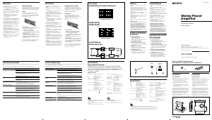
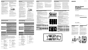
First, place the unit where you plan to install it, and
mark the positions of the four screw holes on the
surface of the mounting board (not supplied). Then
drill the holes approximately 3 millimeters (mm) in
diameter and mount the unit onto the board with the
supplied mounting screws. The supplied mounting
screws are 15 mm long, therefore, make sure that the
mounting board is thicker than 15 mm.
Installation
Avant l'installation
•Installez l’appareil dans le coffre ou sous un siège.
•Choisissez soigneusement l’emplacement de
montage de façon à ce que l’appareil ne gêne pas les
mouvements normaux du conducteur et ne soit pas
exposé au rayonnement direct du soleil ni aux
conduits de chauffage.
•N’installez pas l’appareil sous le tapis de sol car la
dissipation thermique ne pourrait pas se faire
correctement.
Présentez d’abord l’appareil à l’endroit où vous
voulez l’installer et tracez un repère de
positionnement pour les quatre vis sur la plaque de
montage (non fournie). Percez des trous d’environ 3
millimètres (mm) de diamètre, puis fixez l’appareil à
l’aide des vis fournies. Celles-ci font 15 mm de long;
vérifiez, par conséquent, que la plaque fait au moins
15 mm d’épaisseur.
ø 6 (
1
/4)
270 (10
3
/4)
450 (17
3
/4)
422 (16
5
/8)
282 (11
1
/8)
55 (2
1
/4)
Unit : mm (in.)
Unitè : mm (po.)

Join the conversation about this product
Here you can share what you think about the Sony XM-405EQX Car Amplifier. If you have a question, first carefully read the manual. Requesting a manual can be done by using our contact form.