
a
aa
a
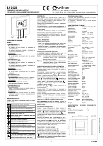
ATENZIONE
- Per una corretta regolazione della temperatura ambiente si
consiglia di installare il termostato lontano da fonti di calore,
correnti d'aria o da pareti particolarmente fredde (ponti
termici). Se si usa una sonda a distanza la nota va applicata
alla sonda e non al termostato.
- Per i collegamenti della sonda usare cavi di sezione minima
1,5 mm² e di lunghezza massima di 25 m. Non passare i cavi
della sonda nelle canaline della rete.
- Collegare l'apparecchio alla rete di alimentazione tramite un
interruttore onnipolare conforme alle norme vigenti e con
distanza di apertura dei contatti di almeno 3 mm in ciascun
polo.
- L'installazione ed il collegamento elettrico del dispositivo
devono essere eseguiti da personale qualificato ed in
conformità alle leggi vigenti.
- Prima di effettuare qualsiasi collegamento accertarsi che la
rete elettrica sia scollegata.
Nell'ottica di un continuo sviluppo dei propri prodotti, il costruttore si riserva il
diritto di apportare modifiche a dati tecnici e prestazioni senza preavviso.
Il consumatore è garantito contro i difetti di conformità del prodotto per 24
mesi dalla data di vendita secondo la Direttiva Europea 1999/44/c. Su
richiesta è disponibile presso il venditore il testo completo della garanzia.
Funzionamento
Il TAE KR0 2C regola la temperatura ambiente in modo
proporzionale-integrale. La tensione di uscita 0 .. 10V si ottiene
mediante la somma della parte proporzionale e della parte integrale.
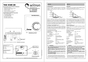
La parte proporzionale si ottiene come dimostrato nel seguente
grafico:
Quando la temperatura ambiente raggiunge il valore del set-point la
tensione di uscita è pari a 5V e diminuisce all’aumentare della
temperatura. La banda proporzionale è regolabile mediante un
trimmer interno da 1°C a 30°C (Fig. 2). La parte integrale è
dipendente dal tempo: quando l’errore tra la temperatura e il set
point è fisso, raggiunge il valore della parte proporzionale in un
intervallo di tempo uguale al tempo di integrazione. il tempo di
integrazione si può selezionare regolando il jumper J1 (Fig. 2).
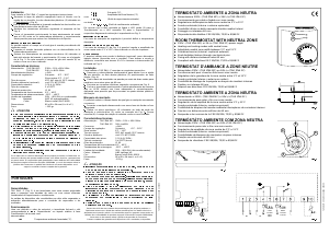
Una riduzione notturna fissa di 4°C si ottiene collegando un
interruttore esterno ai terminali 7 e 8 (la riduzione è attiva quando
l’interruttore è chiuso). Diversi regolatori possono essere connessi in
parallelo allo stesso interruttore di riduzione notturna (per
funzionamento centralizzato, ma la polarità dei collegamenti deve
essere rigorosamente rispettata).
Una sonda (opzionale) per la temperatura esterna può essere
connessa ai terminali 5 e 6, rimuovendo il jumper J2 vicino al
sensore di temperatura interna. Quando si usa il sensore di
temperatura interno il jumper J2 deve essere inserito.
Schema di collegamento
Caratteristiche tecniche
Alimentazione: 24V~/= ±10% 50Hz
Assorbimento elettrico: 0.7VA
Campo di regolazione:
Set point: 6°C .. 30°C
Banda proporzionale: 1°C .. 30°C
Riduzione notturna: 4°C
Tempo di integrazione: disab., 9, 18, 27, 36 min.
Tipo di sonda: Interna: PTC 2030 Ohm @ 25°C
Esterna: STL PTS A150
Precisione: ± 1°C
Risoluzione: ± 0.5°C
Uscita: Tensione di uscita 0 .. 10V=
Max corrente di uscita: 10mA
Grado di protezione: IP 30
Temp. di funzionamento: 0°C .. +40°C
Temp. di stoccaggio: -10°C .. +50°C
Limite di umidità: 20% .. 80% RH (non condensante)
Contenitore:
Materiale: ABS V0 autoestinguente
Colore: Bianco segnale (RAL 9003)
Dimensione: 85 x 85 x 31 mm (L x A x P)
Peso: ~126 gr.
Uscita (V)
10V
5V
Temperatura
ambiente
set point
proporzionale
0V
TAE KR0 2C is a proportional-integral room temperature regulator.
The output voltage (0 .. 10V) is obtained through the sum of a
proportional part and an integral part. The proportional part is
obtained as shown in the graphic be!ow.
When the temperature equals the set point, the output voltage is 5V
and decrease If the temperature is greater. The proportional band is
adjustable through an internal trimmer from 1 to 30°C (see figure 2).
The integral part la time-dependant: when the error between the
temperature and the set point is fixed, It reaches the value of the
proportional part in a time interval wich equals the integration time.
The integration time la selectable by setting the jumper J1 (see
figure 2).
A fixed 4° night reduction is obtained connecting an external switch
on terminals 7 and 8 (the reduction is active when the switch is
closed. Several regulators can be connected in parallel to the same
night reduction external switch (for centralized operation), but the
polarity of the wires must mandatorily be respected.
An (optional) external temperature probe can be connected at
terminals 5 and 6, by removing the jumper J2 near the internal
temperature probe (see figure 2). When using the internal
temperature probe, the jumper J2 must be connected.
Wiring diagram
TAEKR02C 021587B3 211212
ITALIANO
ENGLISH
Output (V)
10V
5V
Room
temperature
set point
proportional band
0V
Riduzione
notturna
Uscita
0 .. 10V=
Sonda
esterna
(opzionale)
Riduzione
notturna
Uscita
0 .. 10V=
Sonda
esterna
(opzionale)
TAE KR0 2C es un regulador proporcional integral de la
temperatura de locales.
El voltaje de salida 0 .. 10V se obtiene mediante la suma de la parte
proporcional y de la parte integral.
La parte proporcional se obtiene como se demuestra en el sig.
gráfico.
Cuando la temperatura alcanza el set point el voltaje de salida es de
5V y disminuye si la temperatura es más alta.
La banda proporcional es regulable mediante un trimmer interno de
1°C a 30°C (Fig. 2).
La parte integral es dependiente del tiempo: cuando el error entre la
temperatura y el set point es fijo, alcanza el valor de la parte
proporcional en un intervalo de tiempo igual al tiempo de
integración.
El tiempo de integración se puede seleccionar regulando el jumper
Salida (V)
10V
5V
Temperatura
ambiente
set point
proporcional
0V
TECHNICAL FEATURES
Power supply: 24V~/= ±10% 50Hz
Power absorption: 0.7VA
Regulation ranges:
Set point: 6°C .. 30°C
Proportional band: 1°C .. 30°C
Night reduction: 4°C
Integration time: disab, 9, 18, 27, 36 min.
Sensor type: Internal: PTC 2030 Ohm @ 25°C
External: STL PTS A150
Precision: ± 1°C
Resolution: ± 0.5°C
Output: Voltage output: 0 .. 10V=
Max. output current: 10mA
Protection grade: IP 30
Operating temperature: 0°C .. +40°C
Storage temperature: -10°C .. +50°C
Humidity limits: 20% .. 80% RH (non condensing)
Case: Material: ABS V0 extinguishing
Color: Signal white (RAL 9003)
Size: 85 x 85 x 31 mm (W x H x D)
Weight: ~126 gr.
a
aa
a
WARNING
- To adjust properly room temperature, install the thermostat
far from heat sources, airstreams or particularly cold walls
(thermal bridges). When the remote sensor is used in
conjunction with the thermostat, then this note is to be
applied to the remote sensor itself.
- For remote version all wirings must be made using wires with
1,5 mm² minimum cross section and no longer than 25 m. Do
not use same duct for signal wires and mains.
- The appliance must be wired to the electric mains through a
switch capable of disconnecting all poles in compliance with
the current safety standards and with a contact separation of
at least 3 mm in all poles.
- Installation and electrical wirings of this appliance must be
made by qualified technicians and in compliance with the
current standards.
- Before wiring the appliance be sure to turn the mains power
off.
In the view of a constant development of their products, the manufacturer
reserves the right for changing technical data and features without prior notice.
The consumer is guaranteed against any lack of conformity for 24 months
from the time of delivery, according to the European Directive 1999/44/EC.
The full text of guarantee is available on request from the seller.
ESPAÑOL
J1 (Fig. 2).
Una reducción nocturna fija de 4°C se obtiene conectando un
interruptor externo a los bornes 7 y 8 (la reducción es activa cuando
el interruptor está cerrado).
Distintos reguladores pueden ser conectados paralelamente al
mismo interruptor de reducción nocturna (para funcionamiento
centralizado, pero la polaridad de los cables debe ser rigurosamente
respetada).
Una sonda (opcional) para la temperatura externa puede ser
conectada a los bornes 5 y 6, removiendo el jumper J2 cerca de la
sonda de la temperatura interna (Fig. 2).
Cuando se usa la sonda de la temperatura interna el jumper J2
debe ser cerrado.
Eschema de collegamento
Características técnicas
Alimentación: 24V~/= ±10% 50Hz
Absorbimiento eléctrico: 0.7VA
Campos de regulación:
Set point: 6°C .. 30°C
Banda proporcional: 1°C .. 30°C
Reducción nocturna: 4°C
Tiempo de integración: discapac., 9, 18, 27, 36 min.
Tipo de sonda: Interna: PTC 2030 Ohm @ 25°C
Externa: STL PTS A150
Precisión: ± 1°C
Resolución: ± 0.5°C
Salida: Voltaje de salida: 0 .. 10V=
Max corriente de salida: 10mA
Grado de protección: IP 30
Temp. de funcionamiento: 0°C .. +40°C
Temp. de almacenamiento: -10°C .. +50°C
Límites de humedad: 20% .. 80% RH (no condensable)
Caja
Material: ABS autoextinguible V0
Color: Blanco señal (RAL 9003)
Dimensiones: 85 x 85 x 31 mm (A x H x P)
Peso: ~126 gr.
a
aa
a
ATENCIÓN
- Para una correcta regulación de la temperatura ambiente
se aconseja instalar el termostato lejos de fuentes de
calor, corrientes de aire o de paredes particularmente frías
(peuntes térmicos). Si se usa una sonda a distancia la nota
anterior se aplica a la sonda y no al termostato.
- Para la conexión de la sonda usar cables de sección
minima 1,5 mm² y longitud max. de 25 m. No pasar los
cables de la sonda en las canaletas de la red eléctrica.
- Conectar el aparato a la red de alimentación mediante un
interruptor omnipolar conforme a las leyes vigentes y con
una distancia de apertura de los contactos de al menos
3 mm en cada uno de los polos.
- La instalación y la conexión eléctrica deben ser realizadas
por personas calificadas y en conformidad con las leyes
vigentes.
- Antes de efectuar cualquier conexión asegúrese que la red
eléctrica esté desconectada.
En la óptica de un continuo desarrollo de los propios productos, el fabricante,
se reserva el derecho de aportar modificaciones a los datos técnicos y
prestaciones sin previo aviso. El consumidor está garantizado contra la falta
de conformidad del producto por 24 meses a partir de la fecha de venta según
la Directiva Europea 1999/44/c. A pedido del cliente está disponible en el
negocio vendedor el texto completo de la garantía.
Reducción
nocturna
Salida
0 .. 10V=
Sonda
externa
(opcional)
TAEKR02C 021587C3 211212


Join the conversation about this product
Here you can share what you think about the Seitron TAEKR02C Thermostat. If you have a question, first carefully read the manual. Requesting a manual can be done by using our contact form.