GB GB GB GB
GB
using an 8 mm drill (size of the screw head). Fasten the guide
rails to the wall
B
with the screws
N
through the holes. Cover
the 8 mm drill holes with the caps
E
(see fig. 20 a + b).
Cleaning and Care
Never use corrosive or abrasive cleaning agents.
Clean the frame using a lint-free, slightly dampened cloth.
If necessary, use mild detergent.
Disposal
The packaging is made entirely of environmentally
friendly materials. Dispose of it at your local recy-
cling centre.
Contact your local municipality for details on how to dispose
of your worn-out product
Declaration of conformity
This product complies with the requirements of the relevant
European and national guidelines. This is confirmed by the
CE mark. The relevant declarations are held by the manufac-
turer.
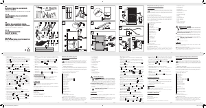
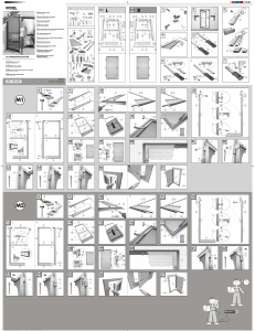
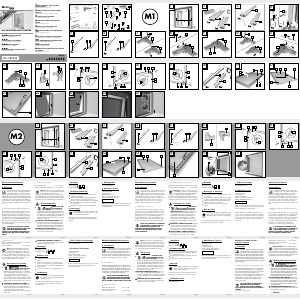
Step 14
Insert the guide rails
B
into the corresponding latches of the
covers
C
and
D
, push them up as far as they will go to
ensure that the guide rails
B
will be seated at the point of
impact between the covers
C
and
D
of the roller screen
enclosure
A
and mount to the wall and though the guide
rail holders
L1
and
L2
using screws
N
(see fig. 19).
Attention: Use a spirit level for the installation.
Now follow step 15 under chapter „Installation inside“.
Note: If the wall quality prevents the guide rails
B
being
optimally flush with the wall, the guide rails
B
can be addi-
tional secured to the wall using a screw
N
.
In this case,
determine the drilling location approximately centred on the
guide rails
B
and drill two holes through the profile walls
using a 4 mm drill bit (see fig. 20). Remove the guide rails
B
, insert the wall plugs and remount the rails
B
. Now drill
holes that are visible in the outer frames of the profile using
an 8 mm drill (size of the screw head). Fasten the guide rails
to the wall
B
with the screws
N
through the holes. Cover
the 8 mm drill holes with the caps
E
(see fig. 20 a+b).
Outside mounting on windows with sill
If the window has a window sill, the guide rail brackets
L
cannot be mounted. Allow the guide rails
B
to rest on the
window ledge. Define a drilling point A approx. 5 cm from
the lower end of each guide rail
B
and drill a hole through
the profiles with a 4 mm drill. Remove the guide
rails
B
, insert the wall plugs and remount the rails
B
. Now
drill holes that are visible in the outer frames of the profile
Attention: The guide rails
B
must always be used in such
a way that the draught shield brush is away from the window.
Now follow step 9 under chapter „Installation inside“.
Step 10
Put the stoppers
G1
and
G2
on the guide rail
B
as described
in step 10 of „Installation inside“ but do not secure them yet.
Step 11
Attach the cover
D
and one roller screen enclosure bracket
M
to the roller roller screen enclosure
A
using a screw
N
.
Attach the second roller screen enclosure bracket
M
to the
other end of the roller screen enclosure
A
, again using one
screw
N
(see fig. 16).
Step 12
Attach the guide rail brackets
L1
and
L2
to the bottom of the
guide rail
B
. Push the stoppers
G1
and
G2
until it hits the
bottom and secure this with a screw driver
N3
(see fig. 17).
Step 13
Using the screws
N1
,
secure the roller screen enclosure
A
through the roller screen enclosure bracket
M
to the front of
the wall, in front of the window reveal. Mount the roller screen
enclosure
A
so the handle strip
A2
is visible in the window
reveal and you are able to reach into the handle strip
A2
to
operate the roller screen.
Attention: Use a spirit level for installation (see fig. 18).
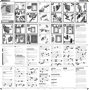
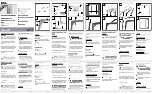
Step 1
Measure the height (h) and the width (w) of your window
opening (see fig. 1).
Step 2
Add 72 mm to the measured width (w) and transfer the result
to the measuring tape on the roller screen enclosure
A
as
described in step 3 of „Installation inside“ (fig. 3).
Follow steps 3 to 6 in the chapter „Installation inside“.
Note: If your window does not have a sill on the outside of
the window
F1
and
F2
, remove the brush seal
A3
before at-
taching the handle strip ends to the bottom of the handle strip
A2
and slide into the designated side groove in the handle
strip
A2
on the side facing the window to ensure optimal
sealing (see detailed image, fig. 16).
Step 7
Subtract 4 mm from the measures height (h) and transfer this
measurement to the guide rails
B
(see fig. 8).
Step 8
Using a hacksaw, cut the guide rails
B
to size (see fig. 8).
Note: Use a mitre box. Then remove any burrs from the
sawn edges using a file.
Hint: Using a pair of pliers, clamp the brush guides at the
top end of the guide rails
B
with the built-in brush seals and
draught shield brushes. This will prevent the brushes from slid-
ing out during use (See fig. 8).
GBGBGBGBGBGB
DE/AT/CH DE/AT/CH DE/AT/CH DE/AT/CH DE/AT/CH DE/AT/CH GB
DE/AT/CH DE/AT/CH DE/AT/CH DE/AT/CH DE/AT/CH DE/AT/CH DE/AT/CH
GB
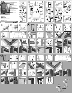
Optional screw mounting: The guide rails
B
may op-
tionally be screw mounted by securing
B
two evenly spaced
screws
N
per guide rail, which will then secure the guide
rails
B
to the window reveal. Use the dowel plugs N2 matching
the screws included in the delivery according to the structure
of the wall. Using a 4 mm drill, first drill a hole through the
rear profile of the guide rails positioned in the reveal
B
(de-
tailed image, fig. 14a), which will provide the markings on
the window reveal. Now remove the guide rails from the re-
veal
B
, insert the matching dowel plugs into the reveal at
the markings and screw
N
the guide rails to the reveal
B
after reinserting them into the latches of the cover
C
and
D
through the drilled holes on the reveal (see fig. 14a).
Step 15
Pull down the blind and hook the handle strip
A2
into the
stoppers
G1
and
G2
.
To do so, pull the handle strip
A2
down
and allow the handle strip
A2
to catch in the retaining collar
of the stoppers
G1
and
G2
(see fig. 15).
To open the roller blind, press down the handle strip
A2
and
then tilt it outwards away from your body a little to unhook it.
Allow the fibre glass fabric
A1
to slowly roll back into the
blind enclosure.
Optional outside mounting
If you don not have the option of installing the roller blind in
your window reveal, you can mount it on the wall, in front of
the reveal.
Step 11
Attach the two bow springs
H
to the cover
C
(see fig. 11).
Note: Omit this and the next step for external installation.
Step 12
Attach two bow springs
H
to the cover
D
and attach this
together with the spiral spring
I
to the roller screen enclosure
A
(see fig. 12). Keep it firmly pressed against the roller
screen enclosure
A
.
Step 13
Keeping the cover
D
firmly pressed to the roller screen en-
closure
A
, clamp the enclosure
A
into the wall reveal (see
fig. 13).
Attention: Be sure the roller screen enclosure
A
is correctly
mounted, meaning the clearance to the outer edge of the
wall is even across the entire width.
Step 14
Attach the double.sided adhesive strip
K
to the guide rails
approx. 2 cm from the bottom edge
B
. Remove the protective
foil (see detailed image 1, fig. 14). Insert the left and right
guide rails
B
into the respective latch of the cover
C
and
D
and align by pushing them up into the latches of the cover
C
and
D
in the window reveal (fig. 14). Be sure that the
draught shield brush is away from the window. Verify that the
guide rails
B
are correctly aligned, meaning the back of the
roller screen enclosure
A
and the back of the guide rails
B
form one surface, thus being evenly spaced from the outer
edge of the wall. You may now firmly press the guide rails
B
to secure them to the wall (see fig. 14).
Step 8
Subtract 46 mm from the measured height (H) and transfer
this measurement to the two guide rails
B
. Using a hacksaw,
cut the guide rails
B
to size (see fig. 8).
Note: Use a mitre box for this purpose. Then remove any
burrs from the sawn edges using a file.
Hint: Using a pair of pliers, clamp the brush guides at the top
end of the guide rails
B
with the built-in brush seals and
draught shield brushes. This will prevent the brushes from
sliding out during use (fig. 8).
Attention: The guide rails
B
must always be used in such
a way that the draught shield brush is away from the window
Step 9
Combine each stopper
G1
and
G2
with a clamp plate
G3
by
loosely securing the clamp plate
G3
to the back of the stop-
pers
G1
and
G2
with the locating screw
N3
through so that
they can still move (fig. 9).
Step 10
Put a stopper
G1
and
G2
on each guide rail
B
by inserting
the stoppers‘
G1
and
G2
clamp plate
G3
from the bottom
into groove provided in the guide rail
B
so that the stoppers
G1
and
G2
lie on the groove in the guide rail
B
. Be sure
that the retaining collar is on the opposite side of the draught
shield brush, the brush with the long bristles.
Align the stoppers
G1
and
G2
straight with the guide rails
B
and secure this with the locating screw
N3
(fig. 10).
Step 4
Slightly pull out the fibre glass fabric
A1
and wrap around
the roller screen enclosure
A
so the fabric
A1
cannot return
to the roller screen enclosure
A
(fig. 3).
person help you with the installation. Ensure the roller screen
enclosure
A
, the fibre glass fabric
A1
and the handle strip
A2
on the side with the anti-glare cap line up. Now saw
through the roller screen enclosure
A
, the fibreglass fabric
A1
and the handle strip
A2
all in one with a hacksaw, and
sawing square (see fig. 4).
Note: Use a mitre box for this purpose. Then polish the inter-
face with a file and remove the aluminium filings with a paint
brush.
Step 5
Now screw
N
the cover
C
to the interface of the roller screen
enclosure
A
(see fig. 5).
Step 6
Thread the cord
F3
in to the groove provided in the handle
strip
A2
. Attach the right and left handle strip end parts
F1
and
F2
onto the handle strip
A2
(see fig. 6).
Step 7
Attach the self-adhesive bush seal
J
,
centred on the ceiling
side of the roller screen enclosure
A
(see fig. 7) and trim off
any excess.
Note: Omit this step for external installation.
Installation inside
Verify your window reveal is suitable for this product prior to
installation. Also be sure not to exceed or be short of the
specified reveal sizes.
Note: If your window opens outwardly, you can also mount
the roller blind to the inside of the window or to the reveal.
Step 1
Measure the height (h) depth (d) and width (w) of your window
reveal (see Fig. 1).
Attention: Please also consider any differences in length,
as window reveals are not always square, particularly in older
buildings.
Step 2
Remove the self-adhesive bush seal
J
from the inside of the
handle strip
A2
(see fig. 2).
Step 3
Transfer the dimensions of the measured width (w) to the
measuring tape on the roller screen enclosure
A
. Measure
with the measuring tape and draw a line for the cut (see fig. 3).
Attention: The measuring tape already allows for the end
cap
and spiral spring
I
. The enclosures
A
can be cut to
a maximum of 70 cm regardless of the imprinted measuring
tape length. In this case shift the measuring tape left beyond
the imprinted 110 cm and mark the measured size.
Technical Data
Max. window reveal dimensions: 130 x 160 cm (w x h)
Minimum reveal width: 70 cm
Minimum reveal depth: 3.5 cm
The reveal is the wall opening where the window frame is
installed.
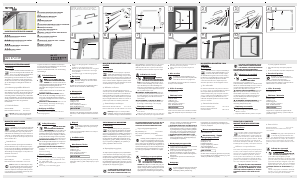
Safety information
DANGER TO LIFE AND
RISK OF ACCIDENTS FOR INFANTS
AND CHILDREN! Never leave children un-
attended with the packaging material or the product. The
packaging material presents a suffocation hazard and
there is a risk of loss of life from strangulation. Children
frequently underestimate the dangers. Please keep children
away from the device at all times. This product is not a toy.
DANGER TO LIFE! Do not lean too far
out of the window during product installation, removal or
cleaning.
CAUTION! RISK OF INJURY! Please ensure that no
parts are damaged and that all parts are correctly as-
sembled. Incorrect assembly could lead to injury. Dam-
aged parts could impact safety and function.
assemble the product if any of the included items listed below
are missing.
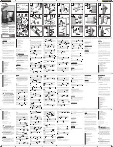
A
1 Bind enclosure
A1
1 Fibreglass fabric „PerfectView“
A2
1 Handle strip
A3
1 Brush seal handle strip
B
2 Guide channels incl.
- brush seal and
- draught shield brush (with long bristles)
C
1 End cover
D
1 End cover
E
4 Caps
F1
1 Handle strip end part right
F2
1 Handle strip end part left
F3
1 Cord
G1
1 Stopper right
G2
1 Stopper left
G3
2 Clamping plate
H
4 Bow springs
I
1 Spiral spring
J
1 Brush seal, self-adhesive
K
2 Double-sided adhesive strips
L1
1 Guide rail holders right
L2
1 Guide rail holders left
M
2 Roller screen enclosure brackets
N
10 Screws 20 mm
N1
2 Screws 35 mm
N2
6 Rawlplugs
N3
2 Locating screw for stopper
1 Installation instructions
Aluminium Insect Screen Blind
Introduction
Congratulations! You have purchased a high-qual-
ity product. Familiarise yourself with the product
prior to assembly. Carefully read the following as-
sembly instructions and safety advice. Only use the product
as described and for the indicated purpose. Keep the instruc-
tions in a safe place, you might need them later. If you pass
the product on to anyone else, please ensure that you also
pass on all the documentation with it.
Intended use
This product is intended to protect against insects and flies in
private residential areas. Any use other than previously men-
tioned or any product modification is prohibited and can
lead to injuries and / or product damage. The manufacturer is
not liable for damage caused by improper use. The product
is not intended for commercial use.
Description of parts and contents
Note: Be careful not to inadvertently throw away any as-
sembly materials whilst unpacking. Immediately after unpack-
ing please check the package contents for completeness and
if all parts and the product are in good condition. Do not
Konformitätserklärung
Dieser Artikel erfüllt die Anforderungen der geltenden euro-
päischen und nationalen Richtlinien. Dies wird durch
CE-Kennzeichnung bestätigt. Entsprechende Erklärungen sind
beim Hersteller hinterlegt.
Montagevideo
www.smartmaxx.info
Hersteller / Service
Smartmaxx GmbH
Inselstraße 27
D-04103 Leipzig
Hotline: +49 (0) 341 99 99 43 79
IAN 43009
Bitte halten Sie für alle Anfragen den Kassenbon und die Artikel-
nummer (z. B. IAN 12345) als Nachweis für den Kauf bereit.
Bohrpunkt A fest und bohren Sie mit einem 4 mm-Bohrer ein
Loch durch die Profilwände. Entfernen Sie
die Führungsschienen
B
, setzen Sie die Dübel ein und brin-
gen Sie die Führungsschienen
B
wieder an. Bohren Sie nun
die in den äußeren Wangen der Profile sichtbaren Löcher mit
einem 8 mm-Bohrer auf (Größe des Schraubenkopfs). Schrau-
ben Sie die Führungsschienen
B
mit den Schrauben
N
durch die Löcher an der Wand an. Decken Sie die 8 mm-Boh-
rungen mit den Abdeckkappen
E
ab (siehe Abb. 20 a + b).
Reinigung und Pflege
Verwenden Sie keinesfalls ätzende oder scheuernde
Reinigungsmittel.
Reinigen Sie den Rahmen mit einem fusselfreien, leicht
angefeuchteten Tuch.
Verwenden Sie ggf. ein mildes Reinigungsmittel.
Entsorgung
Die Verpackung besteht aus umweltfreundlichen
Materialien. Entsorgen Sie diese in den örtlichen
Recyclingbehältern.
Möglichkeiten zur Entsorgung des ausgedienten Produkts
erfahren Sie bei Ihrer Gemeinde oder Stadtverwaltung
Abschlussdeckeln
C
und
D
der Rollokassette
A
Stoß an
Stoß sitzen und schrauben diese mit den Schrauben
N
durch die Führungsschienenhalter
L1
und
L2
an der Wand
fest (siehe Abb. 19).
Achtung: Verwenden Sie zur Montage eine Wasserwaage.
Befolgen Sie nun die Schritt 15 des Kapitels „Montage in der
Fensterlaibung“.
Hinweis: Falls die Mauerbeschaffenheit ein optimales
Abschließen der Führungsschienen
B
mit dem Untergrund
verhindert, können die Führungsschienen
B
zusätzlich mit je
einer Schraube
N
an der Mauer befestigt werden. Legen
Sie hierzu die Bohrpunkte in den Führungsschienen
B
fest
und bohren Sie mit einem 4 mm-Bohrer je zwei Löcher durch
die Profilwände (siehe Abb. 20) in die Mauer. Entfernen Sie
die Führungsschienen
B
, setzen Sie die Dübel ein und bringen
Sie die Führungsschienen
B
wieder an. Bohren Sie nun die
in den äußeren Wangen der Profile sichtbaren Löcher mit einem
8 mm-Bohrer auf (Größe des Schraubenkopfs). Schrauben
Sie die Führungsschienen
B
mit den Schrauben
N
durch
die Löcher an der Wand an. Decken Sie die 8 mm-Bohrungen
mit den Abdeckkappen
D
ab (siehe Abb. 20 a + b).
Montage außerhalb der
Fensterlaibung bei Fenstern mit Sims
Ist das Fenster mit einem Sims ausgestattet, können die Füh-
rungsschienenhalter
L
nicht montiert werden. Lassen Sie die
Führungsschienen
B
auf dem Sims aufstehen. Legen Sie
ca. 5 cm vom unteren Ende der Führungsschienen
B
je einen
Schritt 10
Versehen Sie die Führungsschienen
B
mit den Stoppern
G1
und
G2
, wie in Schritt 10 „Montage in der Fensterlaibung“
beschrieben, fixieren diese aber noch nicht.
Schritt 11
Montieren Sie den Abschlussdeckel
D
und einen Rollokas-
settenhalter
M
mit einer Schraube
N
an die Rollokassette
A
.
Schrauben Sie den zweiten Rollokassettenhalter
M
ebenfalls
mit einer Schraube
N
an die andere Seite der Rollokassette
A
(siehe Abb. 16).
Schritt 12
Stecken Sie die Führungsschienenhalter
L1
und
L2
unten auf
die Führungsschienen
B
. Schieben Sie die Stopper
G1
und
G2
bis zum Anstoß nach unten und stellen diese durch Fest-
drehen der Fixierschrauben
N3
fest (siehe Abb. 17).
Schritt 13
Schrauben Sie die Rollokassette
A
mit den Schrauben
N1
durch die Rollokassettenhalter
M
frontal an die Wand vor die
Fensterlaibung. Montieren Sie die Rollokassette
A
so, dass
die Griffleiste
A2
in der Fensterlaibung sichtbar ist und Sie in
die Griffleiste
A2
greifen können, um das Rollo zu bedienen.
Achtung: Verwenden Sie zur Montage eine Wasserwaage
(siehe Abb. 18).
Schritt 14
Fädeln Sie die Führungsschienen
B
jeweils in die Zungen
der Abschlussdeckel
C
und
D
ein, schieben diese bis zum
Anschlag hoch, so dass die Führungsschienen
B
mit den
Hinweis: Falls bei Ihrem Fenster auf der Außenseite kein
Sims vorhanden ist, ziehen Sie, um ein optimales Abdichten
zu gewährleisten, vor Anbringen der Griffleiste-Abschlussteile
F1
und
F2
die Bürstendichtung
A3
unten an der Griffleiste
A2
heraus und schieben diese in die seitliche, hiefür vorgesehene
Nut in der Griffleiste
A2
auf der zum Fenster gewandten
Seite (siehe Detailbild, Abb. 16).
Schritt 7
Zählen Sie von der gemessenen Höhe (H) 4 mm hinzu und
übertragen Sie das Maß auf die Führungsschienen
B
(siehe
Abb. 8).
Schritt 8
Schneiden Sie mit einer Eisensäge die Führungsschienen
B
zurecht (siehe Abb. 8).
Hinweis: Verwenden Sie eine Gehrungslade. Entgraten Sie
anschließend die Schnittkanten mit einer Feile.
Tipp: Verklemmen Sie mit Hilfe einer Zange die Bürstenfüh-
rungen am oberen Ende der Führungsschienen
B
mit den
integrierten Bürstendichtungen und Windschutzbürsten. So
verhindern Sie ein Herausrutschen der Bürsten während des
Gebrauchs (siehe Abb. 8).
Achtung: Die Führungsschienen
B
müssen immer so zum
Einsatz kommen, dass die Windschutzbürste vom Fenster
weg liegt (Bürste mit langen Borsten)
Befolgen Sie nun die Schritt 9 des Kapitels „Montage in der
Fensterlaibung“.
Schritt 15
Ziehen Sie das Rollo herunter und haken Sie die Griffleiste
A2
in die Stopper
G1
und
G2
ein. Dazu ziehen Sie die Griff-
leiste
A2
nach unten und lassen die Griffleiste
A2
in die Hal-
tenasen der Stopper
G1
und
G2
einrasten (siehe Abb. 15).
Um das Rollo zu öffnen, drücken Sie die Griffleiste
A2
etwas
nach unten und kippen sie dann zum Aushaken vom eigenen
Körper weg nach außen. Das Fiberglasgewebe
A1
langsam
in den Rollokasten zurückrollen lassen.
Alternative Montage vor der
Fensterlaibung auf die Mauer
Haben Sie keine Möglichkeit das Rollo in der Fensterlaibung
einzubauen, können Sie es auch vor die Fensterlaibung auf
die Mauer montieren.
Schritt 1
Messen Sie die Höhe (H) und die Breite (B) Ihrer Fensterlai-
bung aus (siehe Abb. 1).
Schritt 2
Zählen Sie zur gemessenen Breite (B) 72 mm hinzu und über-
tragen Sie das Ergebnis auf das Maßband der Rollokassette
A
,
wie in Schritt 3 „Montage in der Fensterlaibung“ beschrieben
(Abb. 3).
Befolgen Sie nun weiter die Schritte 3 bis 6 des Kapitels
„Montage in der Fensterlaibung“.
darauf, dass die Haltenase gegenüber der Seite der Wind-
schutzbürste, der Bürste mit den langen Borsten, liegt.
Richten Sie die Stopper
G1
und
G2
mit den Führungsschienen
B
bündig aus und stellen diese durch Festziehen der Fixier-
schraube
N 3
fest (Abb. 10).
Schritt 11
Stecken Sie zwei Bogenfedern
H
auf den Verschlussdeckel
C
auf (siehe Abb. 11).
Hinweis: Dieser und der nächste Schritt entfallen bei der
Montage außerhalb der Laibung.
Schritt 12
Stecken Sie zwei Bogenfedern
H
auf den Verschlussdeckel
C
auf und setzen diesen zusammen mit der Spiralfeder
I
auf
die Rollokassette
A
(siehe Abb. 12). Halten Sie diesen ge-
gen die Rollokassette
A
gedrückt fest.
Schritt 13
Klemmen Sie nun, während Sie den Verschlussdeckel
D
gegen die Rollokassette
A
gedrückt festhalten, die Rollokas-
sette
A
in die Mauerlaibung (siehe Abb. 13).
Achtung: Vergewissern Sie sich, dass die Rollokassette
A
korrekt montiert ist, das heißt, über die gesamte Breite einen
gleichmäßigen Abstand zur Mauer-Außenkante hat.
Schritt 14
Kleben Sie das doppelseitige Klebeband
K
ca. 2 cm von
der Unterkante auf die Führungsschienen
B
. Entfernen Sie
die Schutzfolie (siehe Detailbild 1, Abb. 14). Fädeln Sie die
Führungsschienen
B
links und rechts in die jeweilige Zunge
Hinweis: Dieser Schritt entfällt bei der Montage außerhalb
der Laibung.
Schritt 8
Ziehen Sie von der gemessenen Höhe (H) 46 mm ab und
übertragen Sie das Maß auf die beiden Führungsschienen
B
.
Schneiden Sie mit einer Eisensäge die Führungsschienen
B
zurecht (siehe Abb. 8).
Hinweis: Verwenden Sie hierzu eine Gehrungslade. Entgra-
ten Sie anschließend die Schnittkanten mit einer Feile.
Tipp: Verklemmen Sie mit Hilfe einer Zange die Bürstenfüh-
rungen am oberen Ende der Führungsschienen
B
mit den
integrierten Bürstendichtungen und Windschutzbürsten. So
verhindern Sie ein Herausrutschen der Bürsten während des
Gebrauchs (Abb. 8).
Achtung: Die Führungsschienen
B
müssen immer so zum
Einsatz kommen, dass die Windschutzbürste vom Fenster
weg liegt (Bürste mit langen Borsten).
Schritt 9
Kombinieren Sie die Stopper
G1
und
G2
mit je einer Klemm-
platte
G3
, indem Sie die Klemmplatten
G3
mit Hilfe der Fixier-
schrauben
N 3
locker an den Rückseiten der Stopper
G1
und
G2
befestigen, so dass diese noch beweglich bleiben (Abb. 9).
Schritt 10
Versehen Sie jede Führungsschiene
B
mit einem Stopper
G1
und
G2
, indem Sie die Klemmplatte
G3
der Stopper
G1
und
G2
von unten in die dafür vorgesehene Nut an der Führungs-
schiene
B
einschieben, so dass die Stopper
G1
und
G2
auf
der Nut in der Führungsschiene
B
aufliegen. Achten Sie
diesem Fall das Maßband über die angedruckten 110 cm
weiter nach links und markieren das ermittelte Maß.
Schritt 4
Ziehen Sie das Fiberglasgewebe
A1
etwas heraus und schla-
gen Sie es um die Rollokassette
A
, damit das Gewebe
A1
nicht in die Rollokassette
A
zurücklaufen kann (Abb. 3).
Arbeiten Sie ggf. mit einer zweiten Person. Vergewissern Sie
sich, dass die Rollokassette
A
, das Fiberglasgewebe
A1
und
die Griffleiste
A2
der Seite mit der aufgesteckten Blendkappe,
bündig liegen. Sägen Sie nun genau im rechten Winkel mit
einer Eisensäge die Rollokassette
A
, das Fiberglasgewebe
A1
und die Griffleiste
A2
zusammen durch (siehe Abb. 4).
Hinweis: Verwenden Sie hierzu eine Gehrungslade. Entgraten
Sie anschließend die Schnittstelle mit einer Feile und entfernen
Sie Aluspäne mit einem Pinsel.
Schritt 5
Schrauben Sie nun mit der Schraube
N
den Abschlussdeckel
C
auf die Schnittstelle der Rollokassette
A
auf (siehe Abb. 5).
Schritt 6
Fädeln Sie die Zugkordel
F3
in die hierfür vorgersehene Nut
in der Griffleiste
A2
ein. Stecken Sie die Griffleisten-Abschlussteile
F1
und
F2
links rechts auf die Griffleiste
A2
auf (siehe Abb. 6).
Schritt 7
Kleben Sie die selbstklebende Bürstendichtung
J
zentriert
auf die Deckenseite der Rollokassette
A
auf (siehe Abb. 7)
und schneiden das überstehende Ende ab.
Montage in der Fensterlaibung
Vergewissern Sie sich vor der Montage, dass Ihre Fensterlaibung
für dieses Produkt geeignet ist. Überprüfen Sie auch, dass die
angegebenen Laibungsmaße nicht über- oder unterschritten
werden.
Hinweis: Falls Ihr Fenster nach außen zu öffnen ist, können
Sie das Rollo auch auf der Innenseite des Fensters in oder auf
der Laibung montieren.
Schritt1
Messen Sie die Höhe (H), Tiefe (T) und die Breite (B) Ihrer
Fensterlaibung aus (siehe Abb. 1).
Achtung: Berücksichtigen Sie eventuelle Längenunterschiede,
da die Fensterlaibung, vor allem bei Altbauten, nicht immer
gleichmäßig ist.
Schritt 2
Entfernen Sie die selbstklebende Bürstendichtung
J
aus
dem Inneren der Griffleiste
A2
(siehe Abb. 2).
Schritt 3
Übertragen Sie das Maß der gemessenen Breite (B) auf das
Maßband der Rollokassette
A
. Lesen Sie das ermittelte
Maß auf dem Maßband ab und ziehen Sie hier den Strich
für den Schnitt (siehe Abb. 3).
Hinweis: Am Maßband sind der Abschlussdeckel
C2
und
die Spiralfeder
I
bereits berücksichtigt. Die Kassette
A
kann bis auf maximal 70 cm gekürzt werden, unabhängig
von der aufgedruckten Maßbandlänge. Verlängern Sie in
N3
2 Fixierschrauben f. Stopper
1 Montageanleitung
Technische Daten
Max. Maße der Fensterlaibung: 130 x 160 cm (B x H)
Minimale Laibungsbreite: 70 cm
Minimale Laibungstiefe: 3,5 cm
Die Laibung ist die Maueröffnung, in die der Fensterstock
eingebaut ist.
Sicherheitshinweise
LEBENS- UND UN-
FALLGEFAHR FÜR KLEINKINDER UND
KINDER! Lassen Sie Kinder niemals unbeauf-
sichtigt mit Verpackungsmaterial und Produkt. Es besteht
Erstickungsgefahr durch Verpackungsmaterial und Le-
bensgefahr durch Strangulation. Kinder unterschätzen
häufig die Gefahren. Halten Sie Kinder stets vom Produkt
fern. Das Produkt ist kein Spielzeug.
LEBENSGEFAHR! Lehnen Sie sich bei
der Montage, Demontage oder Reinigung nicht zu weit
aus dem Fenster.
VORSICHT! VERLETZUNGSGEFAHR! Stellen Sie
sicher, dass alle Teile unbeschädigt und sachgerecht
montiert sind. Bei unsachgemäßer Montage besteht Ver-
letzungsgefahr. Beschädigte Teile können die Sicherheit
und Funktion beeinflussen.
unmittelbar nach dem Auspacken den Lieferumfang auf Voll-
ständigkeit sowie den einwandfreien Zustand des Produktes
und aller Teile. Montieren Sie das Produkt keinesfalls, wenn
der Lieferumfang nicht vollständig ist.
A
1 Rollokassette
A1
1 Fiberglasgewebe „PerfectView“
A2
1 Griffleiste
A3
1 Bürstendichtung Griffleiste
B
2 Führungsschienen incl.
- Bürstendichtung und
- Windschutzbürste (lange Borsten)
C
1 Abschlussdeckel
D
1 Abschlussdeckel
E
4 Abdeckkappen
F1
1 Griffleisten-Abschlussteil rechts
F2
1 Griffleisten-Abschlussteil links
F3
1 Zugkordel
G1
1 Stopper rechts
G2
1 Stopper links
G3
2 Klemmplatten
H
4 Bogenfedern
I
1 Spiralfeder
J
1 Bürstendichtung, selbstklebend
K
2 Doppelseitige Klebebänder
L1
1 Führungsschienenhalter rechts
L2
1 Führungsschienenhalter links
M
2 Rollokassettenhalterungen
N
10
Schrauben 20 mm
N1
2 Schrauben 35 mm
N2
6 Dübel
Installation video
www.smartmaxx.info
Manufacturer / Service
Smartmaxx GmbH
Inselstraße 27
D-04103 Leipzig
Hotline: +49 (0) 341 99 99 43 79
IAN 43009
For all inquiries about your product, please have your receipt
and the article number (e.g. IAN 12345) ready as your
proof of purchase.
des Abschlussdeckels
C
und
D
ein und stellen Sie diese
durch Hochschieben in die Zungen der Abschlussdeckel
C
und
D
in der Fensterlaibung gerade auf (siehe Abb. 14).
Achten Sie immer darauf, dass die Windschutzbürste vom
Fenster weg liegt. Vergewissern Sie sich, dass die Führungs-
schienen
B
korrekt ausgerichtet sind, das heißt, dass der
Rücken der Rollokassette
A
und der Rücken der Führungs-
schienen
B
eine Fläche bilden und somit einen gleichmäßigen
Abstand zur Mauer-Außenkante aufweisen. Jetzt können Sie
die Führungsschienen
B
zum Ankleben fest an die Mauerlai-
bung drücken (siehe Abb. 14).
Alternative Schraubmontage: Die Führungsschienen
B
können alternativ auch geschraubt montiert werden, indem
Sie je Führungsschiene
B
zwei Schrauben
N
in gleichem
Abstand verteilt anbringen, mit denen Sie die Führungsschie-
nen
B
an die Fensterlaibung anschrauben.
Verwenden Sie die mitgelieferten Dübel N2 und die
mitgelieferten Schrauben. Bohren Sie zuerst mit einem
4 mm-Bohrer ein Loch durch die rückwärtige Profilwand der
in der Laibung sitzenden Führungsschienen
B
(siehe Detail-
bild, Abb. 14a), dadurch erhalten Sie bereits die entsprechende
Markierung auf der Fensterlaibung. Entfernen Sie nun die
Führungsschienen
B
aus der Laibung, setzen Sie in die Fenster-
laibung an den Markierungen die passenden Dübel und
schrauben die Führungsschienen
B
nach deren erneuten
Einfädeln in die Zungen des Abschlussdeckel
C
und
D
mit
den Schrauben
N
durch die gebohrten Löcher an der Fenster-
laibung an (siehe Abb. 14a).
IAN 43009
Smartmaxx GmbH
Inselstraße 27
D-04103 Leipzig
Version des informations
Stand der Informationen · Last Information Update:
09 / 2013 · Ident.-No.: QA259092013-FR
2
43009_pow_Alu-Insektenschutz-Fensterrollo_FR.indd 2 10.09.13 16:12
brush with long bristles).
Notice doing this step: If necessary, have a second

Join the conversation about this product
Here you can share what you think about the Powerfix IAN 43009 Fly Screen. If you have a question, first carefully read the manual. Requesting a manual can be done by using our contact form.
reply | This was helpful (0)