NH-U9 & -U12
|
Installation Guide
2
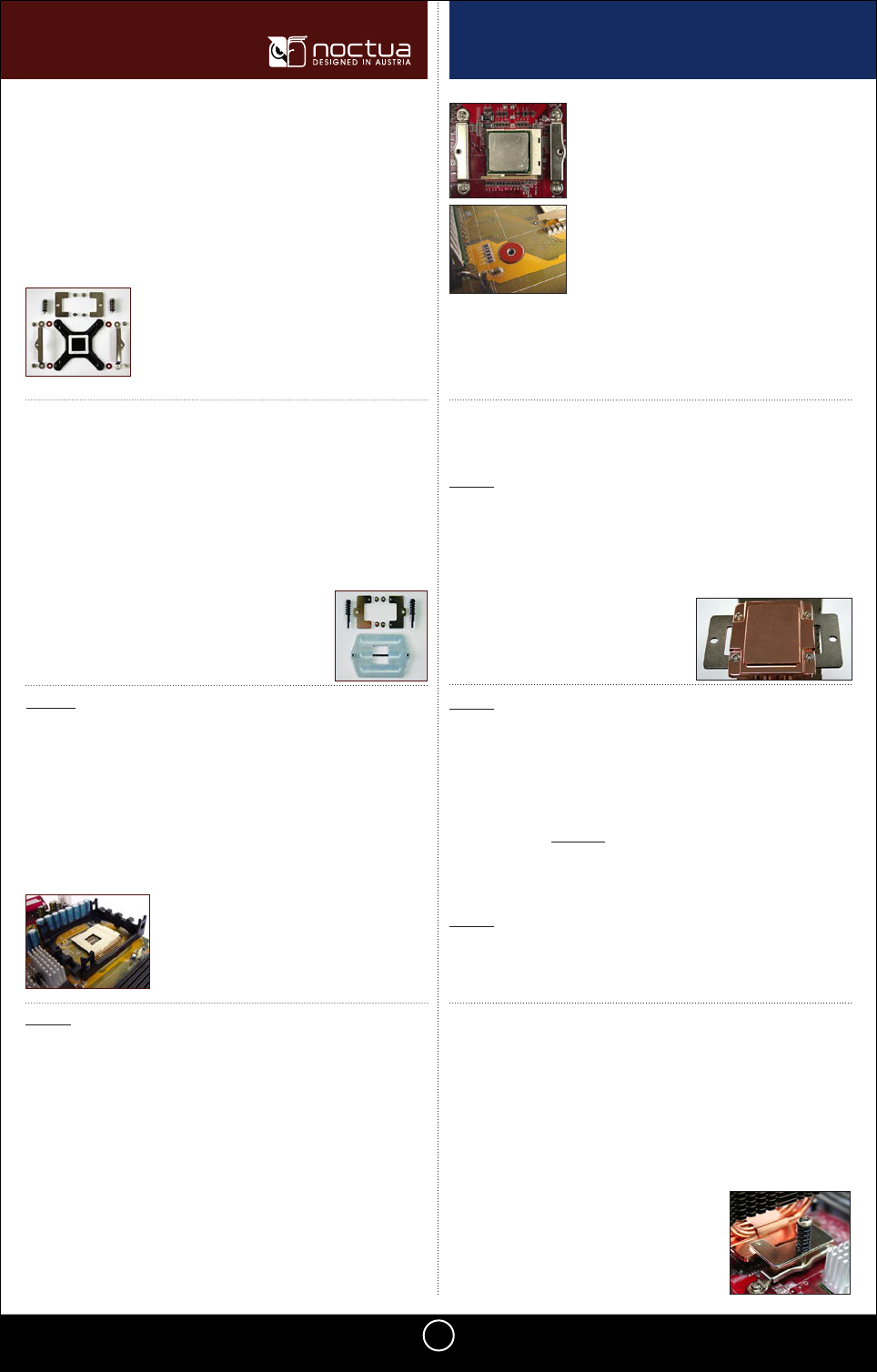
Mounting hardware for LGA 775:
• 1 LGA-backplate (black, x-shaped without cut-out) [PNr.2]
• 2 long, raised mounting bars (fitting the backplane) [PNr.5]
• 8 short screws [SNr1]
• 4 washers
• 2 fastening brackets without bulge [PNr6]
• 2 mid-sized, silver-coloured springscrews [SNr.2]
• 2 pressure springs
Illustration 7
• 1 K8-backplate (silver-coloured, nexagonal with square cut-out in the
center) [PNr.3]
• 2 fastening brackets with bulge [PNr7]
• 4 short screws [SNr1]
• 2 long, black springscrews [SNr.4]
• 2 pressure springs
Illustration 8
Mounting hardware for K8:
In case you want to use the NH-U on an assembled system, you first
have to remove the mainboard from the case as the cooler has to be
screwed together with the backplate on the back side of the mainboard.
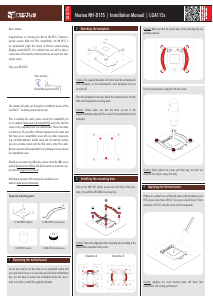
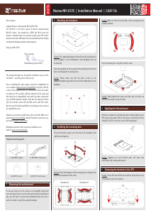
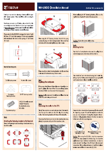
If your mainboard uses a retention module for CPU cooler installation (see
illustration 9), you have to remove it first. Depending on the type of reten-
tion module, it is attached using either screws or plastic pins with bulbous
ends on the back side of the mainboard, which have to be compressed to
Removing the mainboard and
retention module
loosen the module. Should you experience
any difficulties, please consult your main-
board’s manual. If your previous CPU cooler is
attached using a different mounting mecha-
nism, please remove it according to its manual.
2nd Step
Illustration 9
Attaching the backplate on the back side of
the mainboard
Place the backplate [Socket 478: PNr.1, LGA 775: PNr.2] on the back side
of the mainboard, aligning the backplate’s screw sockets with the main-
board’s screwholes.
Caution: The insulated side of the socket 478 backplate [PNr.1] and the
rubber foam square of the LGA backplate [PNr.2] have to face the main-
board!
Now screw the mounting bars [sockel 478: PNr.4, LGA 775: PNr.5] to the
backplate [sockel 478: PNr.1, LGA 775: PNr.2], using small screws [SNr.1]
and washers as shown in illustration 10 (with a socket 478).
a) Socket 478 and LGA 775
3rd Step
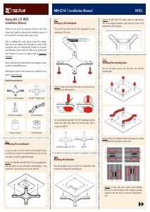
Place the K8 backplate [PNr.3] on the back side of the mainboard, so that
the backplate’s screw sockets stick out through the mainboard’s screw-
holes.
Caution: Make sure that the straight sides of
the the mounting bars face the socket and
the bulgings are pointing outwards as shown
in illustration 10!
Illustration 10
Caution: Don’t forget to put 4 washers be-
tween the mainboard and the mounting
bars to avoid damage to the mainboard.
Illustration 11
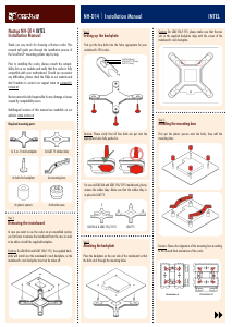
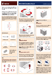
b) AMD K8:
Attaching the fastening brackets to the heat-
sink
Tightly screw the fastening brackets [socket 478 & LGA 775: PNr.6, K8:
PNr.7] to the copper base of the heatsink using 4 short screws [SNr.1] as
shown in illustration 12 (with socket 478 brackets):
Caution: As the fastening brackets [PNr.7] are screwed directly to the
backplate on K8 mainboards, no mounting bars are requiered.
Illustration 12
4th Step
If there are traces of thermal paste or thermal pads on your CPU, please
clean them off first.
Spread a thin coating of the supplied thermal paste on the CPU.
Caution: Applying too much thermal paste will lower the heat conductivity
and cooling performance!
Applying thermal paste
5th Step
Caution: Peel off the protection film at the bottom side of the heatsink
first!
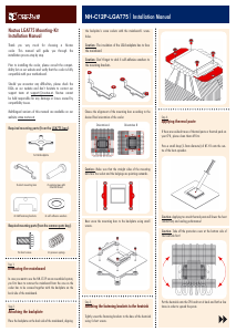
Attaching the heatsink to the cpu
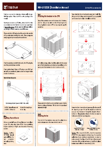
6th Step
Place the heatsink on the CPU, so that the mounting holes of the fastening
brackets [socket 478 & LGA 775: PNr.6, K8: PNr.7] screwed to to the base
of the cooler align with those of the mounting bars [socket 478: PNr.4, LGA
775: PNr.5] (socket 478 & LGA 775) or those of the mainboard and the
backplate [K8: PNr.3] (K8).
Now screw the fastening brackets [socket 478 & LGA 775: PNr.6, K8: PNr.7]
to the mounting bars [socket 478: PNr.4, LGA 775: PNr.5] (socket 478 &
LGA 775) or the backplate [K8: PNr.3] (K8), employing the pressure springs
and the respective screws [Sockel 478: SNr.3, LGA 775: SNr.2; K8: SNr.4] as
shown in illustration 13 (with a sockel 478 mainboard):
Illustration 13


Join the conversation about this product
Here you can share what you think about the Noctua NH-U12 CPU Cooler. If you have a question, first carefully read the manual. Requesting a manual can be done by using our contact form.