
3. ¢È·‚¿ÛÙ ÙË ÌÂÙÚÔ‡ÌÂÓË ÙÈÌ‹ Û Volt.
¶∂ƒπ√Ã∏ ∞∫ƒπµ∂π∞ ∞¡∞.
∞ÓÙ›ÛÙ·ÛË ÂÈÛfi‰Ô˘ 10 M ¶ÂÚÈÔ¯‹ Û˘¯ÓfiÙËÙ·˜
40-1000 Hz. ¶ÚÔÛÙ·Û›· ˘ÂÚÊfiÚÙÈÛ˘: ÂÓÂÚÁfi˜
ÙÈÌ‹ AC 750 V ‹ ̤ÁÈÛÙË ÙÈÌ‹ DC 1000 V (Û˘Ó¯Ҙ
Û fiϘ ÙȘ ÂÚÈÔ¯¤˜).
ŒÓ‰ÂÈÍË: ¢ÈÔÚıˆÌ¤ÓË Ì¤ÛË ÙÈÌ‹ ·ÓÙÈÛÙÔȯ› ÛÙËÓ
ÂÓÂÚÁfi ÙÈÌ‹ ËÌÈÙÔÓÔÂȉԇ˜ Û¯‹Ì·ÙÔ˜.)
À¶√¢∂π•∏:
1. ∞Ó ‰ÂÓ ÁÓˆÚ›˙ÂÙ ÙËÓ ÂÚÈÔ¯‹ Ù¿Û˘, ı·
Ú¤ÂÈ Ó· ‚¿ÏÂÙ ÙÔÓ ‰È·ÎfiÙË FUNCTION
ÛÙËÓ ·ÓÒÙ·ÙË ÂÚÈÔ¯‹ ̤ÙÚËÛ˘ Î·È Ó·
ÌÂÈÒÛÂÙ ÛÙ·‰È·Î¿ ÙËÓ ÂÚÈÔ¯‹, ·Ó ¯ÚÂÈ·ÛÙ›.
2. ∞Ó ÂÌÊ·ÓÈÛÙ› Ë ¤Ó‰ÂÈÍË “1” ÛÙËÓ ÔıfiÓË, Ë
ÌÂÙÚÔ‡ÌÂÓË ÙÈÌ‹ ‚Ú›ÛÎÂÙ·È ÂÎÙfi˜ Ù˘
Ú˘ıÌÈṲ̂Ó˘ ÂÚÈÔ¯‹˜. √ ‰È·ÎfiÙ˘
FUNCTION ı· Ú¤ÂÈ Ó· Ú˘ıÌÈÛÙ› ÛÂ
˘„ËÏfiÙÂÚË ÂÚÈÔ¯‹.
3. ∏ ̤ÁÈÛÙË Ù¿ÛË ÂÈÛfi‰Ô˘ Â›Ó·È 750 V DC,
ÂÓÂÚÁfi˜ ÙÈÌ‹. ∏ ̤ÙÚËÛË ˘„ËÏfiÙÂÚˆÓ Ù¿ÛˆÓ
‰ÂÓ Â›Ó·È ‰˘Ó·Ù‹.
4. ¶ÚÔÛ¤¯ÂÙ ¿Ú· Ôχ fiÙ·Ó ÌÂÙÚ¿Ù ˘„ËϤ˜
Ù¿ÛÂȘ.
10.3 ª¤ÙÚËÛË Û˘Ó¯ԇ˜ Ú‡̷ÙÔ˜ (ADC)
1. ™˘Ó‰¤ÛÙ ÙÔ ª∞Àƒ√ ηÏÒ‰ÈÔ ÛÙËÓ ˘Ô‰Ô¯‹
COM. ™˘Ó‰¤ÛÙ ÙÔ ∫√∫∫π¡√ ηÏÒ‰ÈÔ ÛÙËÓ
˘Ô‰Ô¯‹ “V mA”. °È· ÌÂÁ¤ıË ÌÂٷ͇ 200mA ηÈ
10A, ·Ê·ÈÚ¤Û·ÙÂ ÙËÓ ∫√∫∫π¡∏ ÎÂÊ·Ï‹ ÛÙËÓ
«10A» Ú›˙· ·ÚÔ¯‹˜.
2. µ¿ÏÙ ÙÔÓ ‰È·ÎfiÙË FUNCTION ÛÙËÓ
ÂÈı˘ÌËÙ‹ Ú‡ıÌÈÛË “A” Î·È Û˘Ó‰¤ÛÙ ٷ
ηÏ҉ȷ Û ÛÂÈÚ¿ Ì ÙÔ Î‡Îψ̷ Ô˘ ı¤ÏÂÙ ӷ
ÌÂÙÚ‹ÛÂÙÂ. ¶ÚÔÛ¤ÍÙ ÙË ÛˆÛÙ‹ ÔÏÈÎfiÙËÙ·
(ÎfiÎÎÈÓÔ Â›Ó·È + Î·È Ì·‡ÚÔ Â›Ó·È -), ‰È·ÊÔÚÂÙÈο
Ë ÔıfiÓË ı· ‰Â›¯ÓÂÈ ÙÔ Û‡Ì‚ÔÏÔ ÏËÓ (-) ÚÈÓ
·fi ÙËÓ ÙÈÌ‹. ∏ Ù¯ÓÈ΋ ηÙ‡ı˘ÓÛË Ú‡̷ÙÔ˜
ÙÔ˘ ∫√∫∫π¡√À ηψ‰›Ô˘ ÚÔ˜ ÙÔ ª∞Àƒ√
ηÏÒ‰ÈÔ ÂÌÊ·Ó›˙ÂÙ·È Ù·˘Ùfi¯ÚÔÓ· Ì ÙËÓ ÈÛ¯‡
ÙÔ˘ Ú‡̷ÙÔ˜.
3. ¢È·‚¿ÛÙ ÙËÓ ÙÈÌ‹ Û (milli-) Ampere.
¶∂ƒπ√Ã∏ ∞∫ƒπµ∂π∞ ∞¡∞.
∞ÛÊ¿ÏÂÈ· ˘ÂÚÊfiÚÙÈÛ˘: ·ÛÊ¿ÏÂÈ· 0.2 A/250-V, Ë
ÂÚÈÔ¯‹ 10 A ‰ÂÓ ÚÔÛٷهÂÙ·È.
À¶√¢∂π•∏:
1. ∞Ó ‰ÂÓ ÁÓˆÚ›˙ÂÙ ÙËÓ ÂÚÈÔ¯‹ Ú‡̷ÙÔ˜, ı·
Ú¤ÂÈ Ó· ‚¿ÏÂÙ ÙÔÓ ‰È·ÎfiÙË FUNCTION
ÛÙËÓ ·ÓÒÙ·ÙË ÂÚÈÔ¯‹ ̤ÙÚËÛ˘ Î·È Ó·
ÌÂÈÒÛÂÙ ÛÙ·‰È·Î¿ ÙËÓ ÂÚÈÔ¯‹ ̤ÙÚËÛ˘, ·Ó
¯ÚÂÈ·ÛÙ›.
2. ∞Ó ÂÌÊ·ÓÈÛÙ› Ë ¤Ó‰ÂÈÍË “1” ÛÙËÓ ÔıfiÓË, Ë
ÌÂÙÚÔ‡ÌÂÓË ÙÈÌ‹ ‚Ú›ÛÎÂÙ·È ÂÎÙfi˜ Ù˘
Ú˘ıÌÈṲ̂Ó˘ ÂÚÈÔ¯‹˜ ̤ÙÚËÛ˘. √
‰È·ÎfiÙ˘ FUNCTION ı· Ú¤ÂÈ Ó· Ú˘ıÌÈÛÙ›
Û ˘„ËÏfiÙÂÚË ÂÚÈÔ¯‹ ̤ÙÚËÛ˘.
3. ∏ ÂÚÈÔ¯‹ 20A ‰ÂÓ ÚÔÛٷهÂÙ·È ÌÂ
·ÛÊ¿ÏÂÈ·. °È· ÙÔÓ ÏfiÁÔ ·˘Ùfi, ÌËÓ
Ú·ÁÌ·ÙÔÔț٠̤ÙÚËÛË ÁÈ· ÂÚÈÛÛfiÙÂÚ·
·fi 10 ‰Â˘ÙÂÚfiÏÂÙ·.
10.4 ª¤ÙÚËÛË Ù˘ ·ÓÙ›ÛÙ·Û˘ ( Ohm)
1. ™˘Ó‰¤ÛÙ ÙÔ ª∞Àƒ√ ηÏÒ‰ÈÔ ÛÙËÓ ˘Ô‰Ô¯‹
“COM” Î·È ÙÔ ∫√∫∫π¡√ ηÏÒ‰ÈÔ ÛÙËÓ
˘Ô‰Ô¯‹ “V mA”. (Àfi‰ÂÈÍË: ∏ ÔÏÈÎfiÙËÙ· ÙÔ˘
ÎfiÎÎÈÓÔ˘ ηψ‰›Ô˘ Â›Ó·È “+”.)
2. ƒ˘ıÌ›ÛÙ ÙÔÓ ‰È·ÎfiÙË FUNCTION ÛÙËÓ
ÂÈı˘ÌËÙ‹ ÂÚÈÔ¯‹ ̤ÙÚËÛ˘ “ ”.
¶∂ƒπ√Ã∏ ∞∫ƒπµ∂π∞ ∞¡∞.
∞ÛÊ¿ÏÂÈ· ˘ÂÚÊfiÚÙÈÛ˘: ÂÓÂÚÁfi˜ ÙÈÌ‹ 250 V DC
‹ AC, ÁÈ· ÙÔ Ôχ 15 ‰Â˘ÙÂÚfiÏÂÙ·
3. ™˘Ó‰¤ÛÙ ÙȘ ·Î›‰Â˜ ̤ÙÚËÛ˘ ÛÙÔ ÛÙÔȯ›Ô
Ô˘ ı¤ÏÂÙ ӷ ÌÂÙÚ‹ÛÂÙÂ. µÂ‚·Èˆı›Ù fiÙÈ ÙÔ
ÛÙÔÈ¯Â›Ô ‰ÂÓ Â›Ó·È Û˘Ó‰Â‰Â̤ÓÔ Ì ٷ ¿ÏÏ·
ÛÙÔȯ›·. ªËÓ ·ÁÁ›˙ÂÙ ÙȘ ·Î›‰Â˜ ̤ÙÚËÛ˘
ÁÈ· Ó· ÌËÓ ÂËÚ¿ÛÂÙ ÙȘ ÙÈ̤˜ Ù˘
·ÓÙ›ÛÙ·Û˘.
4. ¢È·‚¿ÛÙ ÙË ÌÂÙÚÔ‡ÌÂÓË ÙÈÌ‹ Û (Ohm).
200 Ω
2K Ω
20K Ω
200K Ω
2MΩ
20MΩ
0,1 Ω
1 Ω
10 Ω
100 Ω
1k Ω
10k Ω
± 0,8% of rdg ± 1 dgt
± 1% of rdg ± 2 dgt
± 0,8% of rdg ± 3 dgt
± 0,8% of rdg ± 1 dgt
± 0,8% of rdg ± 1 dgt
± 1,2% of rdg ± 1 dgt
2mA
2µA
20mA
200mA
1µA
0,1µA
10µA
100µA
± 2% of rdg ± 5 dgt20A 10mA
± 0,8% of rdg ± 3 dgt
2V
20V
200V
1mV
10mV
100mV
750V 1V± 1,2% of rdg ± 3 dgt
Ferm 87
3. Connect the measuring tips to the components to
be measured. Ensure that the component is not
linked to the other components. Do not touch the
measuring tips so as not to affect resistance values.
4. Read off the measured value in (Ohm).
5. While measuring the resistances, current from
the internal battery is used. This current
consumption differs according to the set
measurement range.
HINT:
1. In case the measurand exceeds the highest
value in the set measurement range, the display
shows "1". Select a higher measurement range.
If the resistance is about 1 M and higher, the
measuring device can take a couple of seconds
to stabilise. This is normal in the measurement of
high resistances.
2. If the input is not connected, say in a broken
power circuit, the display shows the figure "1".
This means that the measurement falls outside
the range.
3. In case the resistance to be measured is
connected to a power circuit, you must switch off
the voltage before beginning the measurement
and see that all capacitors are discharged.
10.5 Diodes measurement (Conducting-state
voltage)
1. Connect the BLACK lead to the "COM"
connector socket and the RED lead to the
"V mA" connector socket. (Hint: The polarity of
the red lead is then "+".)
2. Set the FUNCTION switch on the -range and
connect the measuring tips to the diode to be
measured. In the measurement of diodes or
transistors, the polarity of the measuring tips
determines whether the forward direction or the
blocking direction is measured. The displayed
value is the conducting-state voltage drop.
- The tripping current is 0.8 mA.
- In case the measuring tips are not or wrongly
connected to the diode i.e. in the blocking
direction, the display shows the figure 1.
10.6 hFE-Transistor measurement
1. Remove the measuring cable.
2. Set the switch on the hFE setting.
3. Find out whether this transistor is a NPN or PNP
transistor and connect the Emitter- (e), Basic (b)
and collector- (c) cable to the appropriate socket
in the switchgear panel on the front side.
4. The display shows the (approximate) hFE value
for a basic current of 10 µA, V CE 2.8 V.
10.7 Measuring alternating current (AAC)
1. Connect the BLACK lead to the COM connector
socket. Connect the RED lead to the "V mA"
connector socket. For measurements between
200mA and 10A, remove RED lead to “10A”
connector socket.
2. Set the FUNCTION switch on the desired "A~"
setting and connect the leads in series to the
power circuit to be measured. The polarity of the
measuring tips is not relevant.
3. Read off the value in (milli-) Ampere.
RANGE ACCURACY RES.
Overload protection 0.2 A/250-V cut-out, 10-A-
range not protected. Frequency range: 40-1000 Hz.
Display: Corrected centre point (corresponds to the
effective value in a sinusoidal form.)
HINT:
1. In case the current range is previously unknown,
you must set the FUNCTION switch in the
highest measurement range and then reduce
the measurement range gradually if required.
2. If the figure "1" now appears on the display, the
measurand lies outside the range set. The
FUNCTION switch must be switched to a higher
measurement range.
3. The 20A range is not protected with a fuse. Do
not, therefore, measure for longer than 10
seconds.
10.8 Continuity test
1. Connect the BLACK lead to the "COM"
connector socket and the RED lead to the
"V mA" connector socket. (Hint: The polarity of
the red lead is then "+".)
2. Set the FUNCTION switch on the " " range and
connect the measuring tips to the power circuit to
be measured.
3. If the resistance in the power circuit is lower than
50 , the buzzer sounds.
11. SERVICING
CAUTION
• Always remove the battery before servicing and
cleaning of the multimeter. Never use water or
other fluids to clean the device.
• Keep the instrument leads and the multimeter
clean. Some cleaning media and solvents
(petrol, thinner etc.) can attach or dissolve the
plastic. These products contain benzol,
trichloroethane, chlorine, aqueous ammonia
etc.
• Clean the casing regularly using a soft piece of
cloth, preferably after every use.
• Remove the stubborn dirt using moist cloth. Do
not use any solvents such as petrol, alcohol,
ammoniac solution etc. Such substances
damage the plastic parts.
12. PROBLEMS
In case the multimeter does not operate properly,
the cause could be one of these:
± 1,2% of rdg ± 3 dgt
± 2% of rdg ± 3 dgt
2mA
20mA
200mA
1µA
10µA
100µA
± 3% of rdg ± 7 dgt20A 10mA
06 Ferm





Join the conversation about this product
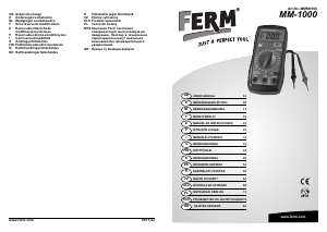
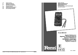
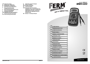
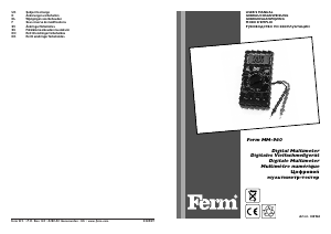
Here you can share what you think about the FERM MMM1008 Multimeter. If you have a question, first carefully read the manual. Requesting a manual can be done by using our contact form.