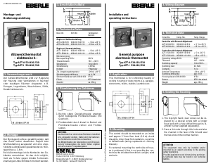
1. Applications
The electronic room temperature controller with floor
temperature limiter is used for single-room control:
• for room heating with limitation to a maximum floor
temperature
• for hot water floor heating systems in combination with
thermo-electric actuator drives actrors normally closed.
The remote sensor F 193720 is required for measuring the
floor temperature.
Features
• Simultaneous room temperature control and floor tem-
perature limitation
• Limitation of floor temperature to a pre-selected max-
imum value
• Nighttime set-back, input for external clock
• Indicator lamps for "controller calls for heat" and for set-
back operation
• 2-poel mains switch
• Mounting in 60mm flush-type box
• Adjustable heating interrupt according standard EN
50559 (not for valves normally open)
2. Description of functions
2.1 Functions
The room temperature is measured by the integrated sen-
sor and is set via the outer dial.
The scale of *…6 corresponds to 5…30 °C.
The floor temperature is measured by the remote sensor
and set via the internal dial (see 2.2).
Interrupts heating after continous heating of 1hr for 5
Minutes (according EN 50559)
Lamps
Red: Controller calls for heat
Green: Set-back mode is activated
Caution-1!
The device may only be opened and installed ac-
cording to the circuit diagram on the device or these
instructions by a qualified electrician. The existing
safety regulations must be observed.
Appropriate installation measures must be taken to
achieve the requirements of protection class II.
This independently mountable electronic device is de-
signed for controlling the temperature in dry and enclo-
sed rooms only under normal conditions. The device
confirms to EN 60730, it works according operating prin-
ciple 1C
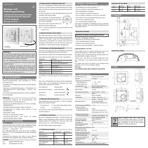
468 931 003 300-9
Mounting and
Operating Instructions
Electronic room temperature controller
with floor temperature limiter
and set-back input
FRe L2A, 517 81 81…
2.2 Limiting the floor temperature
The maximum floor temperature is set via the internal
potentiometer (left to the lamps). The arrow in the poten-
tiometer displays the desired temperature
The floor temperature is preven ted
from exceeding the set value.
The lamps will display the set floor
temperature when the controller is
switched on.
The green lamp indicates the units of
ten, the red one the units from 1-9.
e.g. 35° = green lamp flashes 3 times, then the red lamp
flashes 5 times.
2.3 Call for heat
The amount of heat called for is determined by the two
control values (of the room and the floor). The room tem-
perature will be controlled as long as the floor temperatu-
re is below the selected max. value. If this value is excee-
ded, the heating will be switched off until the floor has
cooled down.
2.4 Functions of the set-back input TA
The TA input is used to set various set-back functions, refer
to table below.
The functions are selected via the mains sine half-waves.
The functions correspond to the "Pilot wire" specifica-tion.
Half-wave Function
none no set-back
both set-back acc. to J2
positive control off
negative anti-freeze = 5°C
both pulsed short set-back by 1°C
both pulsed long set-back by 2°C
The anti-freeze function regulates to a temperature of 5°C.
This multi-function input makes it possible to acti-vate
controller functions by means of the various half-waves of
the mains AC voltage:
Normal operation: input open – – – –
Temp. set-back: both half-waves
Ä
Anti-freeze: negative half-wave Å
Heating off: positive half-wave Ç
2.5 Selecting the set-back temperature
By means of the J2 jumper it is possible to select 3° or 5°..
J2 closed* set-back by 5°C
J2 open set-back by 3°C
* = factory pre-set
The temperature set externally via the dial is reduced by
this value.
2.6 Fault of the floor sensor
If a sensor fault (short-circuit or break) occurs, the control-
ler will switch to fault mode. The heating will function with
max. 30% of the energy (operation for 30% of the time).
This provides frost- and overheat protection.
In the event of a sensor fault, both lamps will flash.
2.7 Function of the lamps
Function Lamp green Lamp red
Heating is on on
Set-back mode on
Floor sensor fault flashes flashes
max. floor temp. flashes flashes
(for higher (for lower
digit) digit)
3. Mounting / Commissioning
The controller should be mounted at a point in the room
which:
• can be easily accessed
• is free of curtains, cabinets, shelves, etc.
• allows free air circulation
• is not exposed to direct sunlight
• is not draughty (when doors or windows are opened)
• is not directly influenced by the source of heat/cold
• is not located on an outer wall
• is approx. 1.5 m above the floor.
Electrical connection
Perform the steps described below:
• Pull off the temperature dial
• Release the fixing screw
• Remove the upper part of the casing
• Connect acc. to circuit diagram (see bottom of casing)
After power on, the adjusted maximum floor temperature
will be displayed see 2.2.
Floor sensor F 193 720
The remote sensor must be mounted in such a way that
the temperature to be limited can be correctly de-
tected.
The remote sensor should be installed in a protective tube.
This will facilitate future replacement.
Do not install the sensor close to power lines. In other
cases a shilded cable has to be used.
The sensor can be extended to max. 50 m by means of a
cable suitable for mains voltage.
Caution !
The sensor lines are on mains voltage (230 V).
4. Technical data
Order designation FRe L2A, FRe L2A/50
EDP No. 517 8181…
Temperature setting range
Room temperature *…6 (5…30ºC)
Floor temperature 20…50ºC
Indicator lamp red Controller calls for heat
green Set-back temperature
Power switch 2-pole
Supply voltage 230 V AC (207…253 V)
50/60 Hz
Output Relay make contact
Switching current 10mA…16 A cosϕ = 1;
10 mA… 4 A cosϕ = 0.6
Control algorithm Proportional controller
(similar to continuous
through PWM)
Switching temperature
differential ~1°C
Temperature sensor
for room temperature internal
for floor temperature Type F 193 720 (length 4 m,
can be extended to 50 m)
Temperature set-back
for room temperature 3K or 5 K selectable s. 2.5
via external timer
Range limitation in the dial
Degree of protection
of casing IP30
Safety class II (see Caution-1)
Pollution degree 2
Software class A
Calculation impulse voltage 4 kV
Ball pressure test
temperature 75 ± 2 °C
Voltage and Current for
the for purposes of inter-
fernce measurements 230V, 0.1 A
Ambient temperature 0…40ºC
Storage temperature –25…70 ºC
Weight 90 g
Energy class IV = 2 %
(acc. EU 811/2013, 812/2013, 813/2013, 814/2013)
Caution! De-energize the electric circuit first
Sensor characteristics
10°C 66.8 kΩ 30°C 26.3 kΩ
20°C 41.3 kΩ 40°C 17.0 kΩ
25°C 33 kΩ 50°C 11.3 kΩ
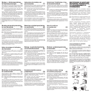
5. Circuit diagram
Position of the jumpers
6. Dimensions
cover one partcover two parts,
50 x 50 mm
This product should not be disposed of with
household waste.
Please recycle the products where facilities for
electronic waste exist. Check with your local
authorities for recycling advice.


Join the conversation about this product
Here you can share what you think about the Eberle FRe L2A Thermostat. If you have a question, first carefully read the manual. Requesting a manual can be done by using our contact form.