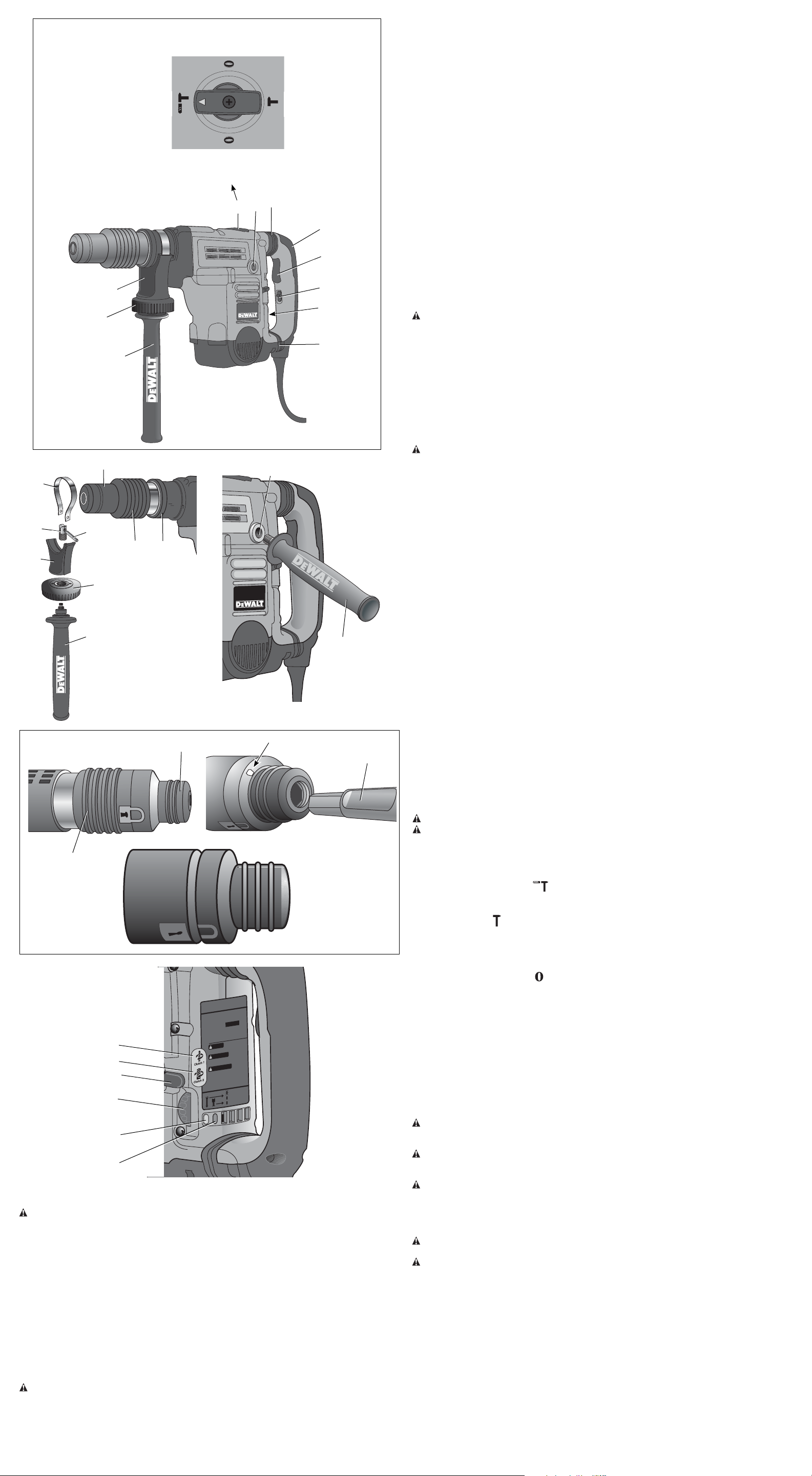
COMPONENTS (Fig. 1)
WARNING: Never modify the power tool or any part of it. Damage or personal injury could
result.
A. Trigger switch F. Mode selector
B. Lock-on slider G. Electronic Speed and impact control dial
C. Side handle H. Clamp knob
D. Main handle I. Rear side handle position
E. Active vibration control
INTENDED USE
These heavy-duty rotary hammers have been designed for professional hammerdrilling, and
chipping at various work sites (i.e., construction sites). DO NOT use under wet conditions or in
presence of flammable liquids or gases.
These heavy-duty rotary hammers are professional power tools. DO NOT let children come into
contact with the tool. Supervision is required when inexperienced operators use this tool.
ASSEMBLY AND ADJUSTMENTS
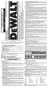
Side Handle (Fig. 1)
WARNING: To reduce the risk of personal injury, ALWAYS operate the tool with the side
handle properly installed and securely tightened. Failure to do so may result in the side handle
slipping during tool operation and subsequent loss of control. Hold tool with both hands to
maximize control.
The side handle clamps to the front barrel (collar) and may be rotated 360° to permit right
or left-hand use. For operating convenience, the side handle can be installed in front or rear
positions.
TO MOUNT IN FRONT POSITION (FIG. 2)
1. Unscrew the side handle (C) and disassemble the side handle clamp (J).
2. Snap the steel ring (K) over the collar (L) behind the tool holder (M). Squeeze both ends of
the steel ring together. Mount the bushing (N) and insert the pin (O).
3. Slide the side handle clamp (J) over the bushing and screw on the clamp knob (H)–do not
tighten.
4. Screw the side handle (C) into the clamp knob (H) and tighten.
5. Rotate the side handle mounting assembly to the desired position. For hammerdrilling
horizontally with a heavy drill bit, place the side handle assembly at an angle of approximately
20° to the tool for optimum control.
6. Lock the side handle mounting assembly in place by tightening the clamp knob (H).
TO MOUNT IN REAR POSITION (FIG. 3)
1. Unscrew the side handle (C) and remove it from the side handle mounting assembly. Leave
the side handle mounting assembly in the front position.
2. Screw the side handle directly into one of the rear side handle positions (I) on either side of
the tool.
Active Vibration Control (Fig. 1)
D25602, D25651, D25831, D25851
For best vibration control, hold the tool with one hand on the main handle (D) and the other hand
on the side handle (C). Apply just enough pressure so the damping device on the main handle
is approximately mid stroke. The hammer only needs enough pressure to engage the active
vibration control. Applying too much pressure will not make the tool drill or chip faster and active
vibration control will not engage.
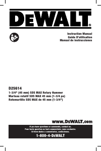
Inserting and Removing Spline Drive Accessories
(Fig. 4)
D25553, D25651, D25851
WARNING: To reduce the risk of serious personal injury, turn tool off and disconnect tool
from power source before making any adjustments or removing/installing attachments or
accessories.
1. Insert the bit shank into the tool holder (M) as far as it will go. The groove on the chisel shank
(Q) must be aligned with the symbol (R) on the toolholder. If inserted correctly, the locking
sleeve (P) moves back to the end position and shows a closed lock symbol.
2. Pull on the bit to be sure that it is properly locked.
3. If the chisel groove is not aligned with the symbol, or is not inserted to the complete depth
the lock symbol remains open.
To remove the bit, pull back the locking sleeve and pull the bit out.
Inserting and Removing SDS Max
®
Accessories
D25501, D25602, D25831
WARNING: To reduce the risk of serious personal injury, turn tool off and disconnect tool
from power source before making any adjustments or removing/installing attachments or
accessories.
1. Pull back the locking sleeve (P) and insert the bit shank. The bit shank must be clean.
2. Turn the bit slightly until the sleeve snaps back into position.
3. Ensure the bit is properly engaged.
NOTE: The bit needs to move several centimeters in and out of the tool holder (M) when
properly engaged.
4. To remove the bit, pull back the locking sleeve and pull the bit out.
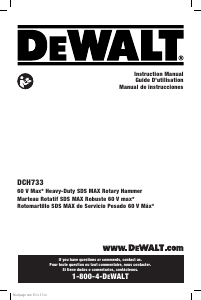
Complete Torque Control (Fig. 5)
D25602, D25651
NOTICE: Always turn the tool off before changing torque control settings or damage to tool may
result.
The Complete Torque Control (CTC) feature of this tool is designed to provide additional control
with a two-stage clutch mechanism.
Clutch Setting 1 (S) is designed for most hammerdrilling applications and is designed to easily
clutch out when the drill bit encounters re-bar or other foreign substances.
Clutch Setting 2 (T) is designed for higher torque applications such as core-bits and deep hole
hammerdrilling and is designed to clutch out at a higher torque threshold.
Move the torque control lever (U) to setting 1 or 2 as needed for application.
NOTE: Allow the motor housing to rotate a little while changing torque.
Each time the tool is plugged in, it will automatically default to clutch setting 1, the most
sensitive setting.
Electronic Speed and Impact Control (Fig. 5)
D25602, D25651, D25831, D25851
The electronic speed and impact control allows the use of smaller drill bits without the risk of
bit breakage, hammerdrilling into light and brittle materials without shattering and optimal tool
control for precise chipping.
To set the control dial, turn the dial (G) to the desired level. The higher the number, the greater
the speed and impact energy. Dial settings make the tool extremely adaptable for many
different appli cations. The required setting depends on the bit size and hardness of material
being drilled.
Mode Selector (Fig. 1)
CAUTION: Never change the mode while the unit is running.
CAUTION: Do not change to hammerdrill mode with chisel bit in tool holder. Personal injury
and damage to tool may result.
The D25501, D25553, D25602, D25651 uses two operating modes. To select the required
operating mode, rotate the mode selector (F) until the arrow points to the hammerdrilling or the
chipping icon. The D25831 and D25851 use only the chipping mode.
HAMMERDRILLING MODE (
)
The tool simultaneously rotates and impacts the work. This mode is appropriate for all concrete
and masonry operations.
CHIPPING MODE (
)
The spindle lock is engaged during chipping mode so the tool impacts the work without
rotating. This mode is appropriate for light chipping, chiseling and demolition applications.
NOTE: In chipping mode, the hammerdrill can also be used as a lever to free a jammed drill
bit.
CHISEL BIT ADJUSTMENT (
)
Turn the mode selector to one of the chisel bit adjustment icons to adjust the chisel to the
desired position. There are 18 possible positions to set the angle of the chisel. After finding the
desired position, slightly maneuver the chisel bit back and forth to ensure the chisel is properly
engaged.
Power Indicator Lights (Fig. 5)
The yellow brush wear indicator LED (V) lights up when the carbon brushes are nearly worn out
indicating that the tool needs servicing within the next 8 hours of use.
The red indicator LED (W) lights up if the lock-on slider (B) is used in any mode except the
chipping mode.
The red indicator LED (W) flashes if there is a fault with the tool or if the brushes are completely
worn (refer to Brushes under Maintenance).
OPERATION
WARNING: To reduce the risk of serious personal injury, turn tool off and disconnect tool
from power source before making any adjustments or removing/installing attachments or
accessories.
WARNING: To reduce the risk of personal injury, ALWAYS ensure workpiece is anchored
or clamped firmly. If hammerdrilling thin material, use a wood “back-up” block to prevent
damage to the material.
WARNING: To reduce the risk of personal injury, ALWAYS operate the tool with the side
handle properly installed and securely tightened. Failure to do so may result in the side
handle slipping during tool operation and subsequent loss of control. Hold tool with both hands
to maximize control.
Proper Hand Position (Fig. 1)
WARNING: To reduce the risk of serious personal injury, ALWAYS use proper hand position
as shown.
WARNING: To reduce the risk of serious personal injury, ALWAYS hold securely in anticipation
of a sudden reaction.
Proper hand position requires one hand on the side handle (C), with the other hand on the main
handle (D).
NOTE: Operating temperature of this tool is 19˚ to 104˚ F (-7 to +40˚ C). Using the tool outside
of this temperature range will decrease the life of the tool.
Trigger Switch (Fig. 1)
To turn the tool on, depress the trigger switch (A). To stop the tool, release the trigger switch.
D25602, D25651
In chipping mode only, lock the trigger switch on, push the lock-on slider (B) upwards while
depressing the trigger switch.
To deactivate the lock-on slider, depress the trigger switch once then release.
The lock-on slider may only be activated in chipping mode. The machine will stop running when
trying to engage the lock-on slider in hammerdrilling mode. The motor will stop if the lock-on slider is
activated when changing from chisel mode into hammerdrilling mode.
D25831, D25851
For continuous operation, move the toggle switch to the on position. To stop continuous
operation, move the toggle switch to the off position.
HAMMERDRILLING MODE
MODE DE MARTEAU PERFORATEUR
MODO TALADRO PERCUTOR
CHIPPING MODE
MODE DE BURINAGE
MODO CINCEL
CHISEL BIT ADJUSTMENT MODE
MODE DE RÉGLAGE DU TRÉPAN ORDINAIRE
MODO DE AJUSTE DE LA BROCA DE CINCEL
CHISEL BIT ADJUSTMENT MODE
MODE DE RÉGLAGE DU TRÉPAN ORDINAIRE
MODO DE AJUSTE DE LA BROCA DE CINCEL
F
E
A
I
G
B
E
C
H
D
FIG. 1
K
J
O
H
C
N
FIG. 2
L
P
M
FIG. 3
C
I
D25602
W
CTC
COMPLETE TORQUE CONTROL
D
E
W
A
L
T INDUSTRIAL TOOL CO., BA
L
TIMORE, MD 21286 USA
FOR SERVICE INFORMA
TION, CALL 1-800-4-D
E
W
A
L
T
ww
w
.D
E
W
A
L
T
.com
SER.
D25XXX
1 3/4" (44mm) SDS MAX
RO
TAR Y HAMMER
AFIN DE MINIMISER
LES RISQUES DE
BLESSURES,
L
’UTILIS
A
TEUR DOIT LIRE LE GUIDE
D’UTILIS
A
TION.TOUJOURS UTILISER UNE PROTECTION
OCULAIRE,
AUDITIVE ET RESPIR
A
TOIRE ADÉQU
A
TE.
UTILISER LA POIGNÉE L
A
TÉRALE.
LEA EL MANUAL DE
INSTRUCCIONES PARA
UN FUNCIONAMIENTO SEGURO. SIEMPRE UTILICE
PROTECCIÓN ADECUADA
PARA LOS OJOS, OÍDOS Y VÍAS
RESPIR
A
TORIAS. SIEMPRE UTILICE EL MANGO LATERAL.
TO REDUCE THE RISK OF INJUR
Y,
USER MUST READ INSTRUCTION
MANUAL. A
LWA
YS USE PROPER EYE, EAR AND
RESPIR
ATO
RY PROTECTION. A
LW
A
YS USE SIDE HANDLE.
Service
Lock-On
B
r
ush Se
rvice
WARNING
AVERTISSEMENT
ADVERTENCIA
FIG. 5
G
V
S
T
U
FIG. 4
M
P
R
Q
J


Join the conversation about this product
Here you can share what you think about the DeWalt D25831K Rotary Hammer. If you have a question, first carefully read the manual. Requesting a manual can be done by using our contact form.