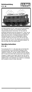
Operating instructions
diesel locomotive DB V 160
During the fifties, the Deutsche Bundesbahn (DB)
began replacing its extensive fleet of steam
locomotives with diesel locomotives. Fast running
diesel engines and hydraulic power transmission
were decided on.
The decisive factor for this choice was the then
considerably more favourable power-weight ra-
tio. In 1956, when available engines had become
powerful enough, the DB had the first one-engined
main-line locomotive designed. As an engine
output of 1600 PS was originally envisaged, the
locomotive was given the series designation V 160.
This was retained, although already the first
prototype locomotives were equipped with 1900
PS engines (1400 kW).
In the years between 1964 and 1968, Krupp,
Henschel, Krauss-Maffei and KHD built a total of
214 series engines in this line. 16-cylinder engines
by Maybach and Mercedes-Benz provided the
power; the maximum speed in the passenger train
service was 120 km/h. Against the background of
renaming the DB-stock in 1968, the extremely
reliable and general purpose locomotive was given
the new series designation 216. Today, numerous
further developments, such as e.g. the 210, the
215 or the 218 count as part of this “family”.
The N-model by BRAWA is equipped with
impressive technical and design details.
2 3 4 5 6 7 8
Inhaltsverzeichnis
Contents
Benennung Seite
Allgemeine Hinweise ....................................... 5
Wartungsarbeiten
• 1. Gehäuse demontieren ............................. 6
• 2. Platinen tauschen,
LED wechseln ......................................... 6
• 3. Motor tauschen ....................................... 6
• 4. Drehgestell ausbauen,
Haftreifen erneuern,
Kupplungsschacht tauschen .................. 6
• 5. Ölen ........................................................ 9
Ersatzteilliste ......................................... 10 – 13
Bestellbeispiel ............................................... 12
Description Page
General information ........................................ 5
Maintenance works
• 1. Dismantling the housing ......................... 8
• 2. Exchanging circuit board,
changing LED ......................................... 8
• 3. Exchanging the motor ............................. 8
• 4. Removing the bogie,
renewing the traction tires,
exchanging the coupling ......................... 8
• 5. Lubricating ............................................. 9
Spare parts list ...................................... 10 – 13
Order example ............................................... 13
Allgemeine Montage- und
Sicherheitshinweise
• Diese Bedienungsanleitung beschreibt
sämtliche Arbeitsvorgänge die zur Wartung
und Instandhaltung notwendig sind. Bitte
lesen Sie diese Bedienungsanleitung bevor
Sie mit den Arbeiten beginnen.
• Bei unsachgemäßem Umgang mit elektri-
schen Bauteilen können diese zerstört
werden. Für entsprechende Arbeiten (z.B.
Platinenwechsel) können Sie sich an Ihren
Fachhändler oder den Hersteller wenden.
• Bei den folgenden Wartungsarbeiten ist die
jeweilige Demontage beschrieben, der
Zusammenbau ist in umgekehrter
Reihenfolge auszuführen.
• Achten Sie beim Zerlegen der Lokomotive
auf die Einbaulage der entsprechenden
Bauteile. Wird ein Bauteil falsch eingebaut
kann dieses zerstört werden oder es kommt
zu Funktionsstörungen im Betrieb.
• Jegliche Kabel oder Verbindungsdrähte die in
diesem Produkt verbaut sind dürfen nicht in
eine Netzsteckdose eingeführt werden.
Lebensgefahr!
General assembly and safety
information
• These operating instructions describe all
work steps necessary for maintenance and
repair. Please read these operating
instructions carefully before you start with
your work.
• In the case of incorrect handling of electrical
components, they may be destroyed. Please
ask your specialist dealer to help with the
necessary work (e.g. changing circuit
boards).
• In the case of maintenance work, the
disassembly is described below, to re-
assemble the tractor reverse the work steps.
• When dismantling the engine make a note
of the mounted position of the individual
parts. An incorrectly mounted part can be
destroyed or operation can be disrupted.
• All cables and connection wires installed in
this product may not be inserted in a mains
socket. Danger!
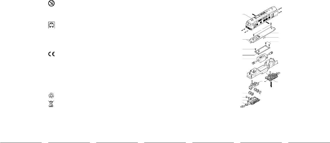
Wartungsarbeiten
1. Gehäuse demontieren (Fig. 1)
Puffer (1) nach vorn abziehen, Gehäuse (2) leicht
spreizen und nach oben abnehmen.
2. Platine tauschen, LED wechseln (Fig. 1)
Gehäuse demontieren, siehe Punkt 1.
Befestigungsschrauben (3) der Platine herausdre-
hen, Kabel ablöten und Platine (4) abnehmen.
Hinweis:
– Bitte kennzeichnen Sie sich wo welches
Kabel an der Platine angelötet war.
Jetzt kann die entsprechende LED (5) an der
Platine abgelötet werden.
Beim Einbau der Platine ist auf den genauen Sitz
der Motorkontaktbleche (6) zu achten.
3. Motor tauschen (Fig. 1)
Gehäuse und Platine demontieren, siehe Punkt 1
und 2.
Befestigungsschrauben (7) der Motorhalterungen
(8) herausdrehen, Motor (9) mit Kardanwelle und
Schnecke nach oben herausziehen.
4. Drehgestell ausbauen, Haftreifen erneuern,
Kupplungsschacht tauschen, (Fig. 1)
– Drehgestell ausbauen
Gehäuse demontieren, siehe Punkt 1.
2 Kabel des entsprechenden Drehgestells an der
Platine ablöten.
Drehgestell (10) vorsichtig nach unten herauszie-
hen – clipst sich selbst aus.
– Haftreifen erneuern
Drehgestell umdrehen, Räder müssen nach oben
zeigen. Snap-in (11) lösen und Rahmen (12) ab-
nehmen, jetzt sind die Räder (13) frei zugänglich
und die Haftreifen (14) können erneuert werden.
– Kupplungsschacht tauschen
Haltebügel (15) ausclipsen, Kupplungsschacht (16)
mit Kupplung (17) entnehmen.
Kupplung aus Kupplungsschacht ausclipsen.
Fig. 1
Maintenance works
1. Dismantle housing (Fig. 1)
Pull off buffer (1) to the front, gently spread housing
(2) open and pull off upwards.
2. Replace board, change LED (Fig. 1)
Dismantle housing, see point 1.
Unscrew fastening screw (3) of board, solder cable
to disconnect and remove board (4).
Note:
– Please mark where which cable was soldered
to the board.
Now solder the corresponding LED (5) to remove
it from the board.
When installing the board, pay attention that the
motor contact plates (6) are sitting properly.
3. Replace motor (Fig. 1)
Dismantle housing and board, see point 1 and 2.
Unscrew fastening screws (7) of the motor bracket
(8), pull motor (9) upwards with cardan shaft and
screw.
4. Remove bogie, replace adhesion tyres,
replace coupling shaft (Fig. 1)
– Remove bogie
Dismantle housing, see point 1.
Solder 2 cables of the corresponding bogie to
disconnect from the board.
Carefully pull bogie (10) out downwards – it unclips
of its own accord.
– Replace adhesion tyres
Turn bogie over. Wheels must point upwards. Undo
snap-in (11) and remove frame (12), now the
wheels (13) are freely accessible and the adhesion
tyres (14) can be replaced.
– Replace coupling shank
Unclip holding strap (15), remove coupling shank
(16) with coupling (17).
Unclip coupling from coupling shank.
Nicht bestimmt für Kinder unter 3
Jahren. Verschluckbare Kleinteile.
Betriebsanleitung aufbewahren!
Not recommended for children under
3 years of age. Small parts may be
swallowed. Retain the operating
instructions!
Zum Betrieb des vorliegenden
Produkts darf als Spannungsquelle
nur ein nach VDE 0551/EN 60742
gefertigter Spielzeug-Transformator
verwendet werden.
Only a toy transformer produced
compliant with VDE 0551/EN 60742
may be used as a voltage source to
operate this product.
Dieses Produkt entspricht den
grundlegenden Sicherheits- und
Gesundheitsanforderungen der
Europäischen Richtlinie für
Spielzeuge (88/378/EWG) unter
Beachtung der Europäischen
Sicherheitsnorm EN 71.
This product conforms to the
fundamental health and safety
requirements of the European
Directive for Toys (88/378/EEC) with
due regard to the European Safety
Standard EN 71.
Elektro- und Elektronikaltgeräte dürfen
nicht in den Hausmüll gelangen. Sie
müssen entsprechend der jeweils
gültigen Länderrichtlinien fachgerecht
entsorgt werden.
Electrical equipment may not reach to
domestic waste. According to the
current terms of the country reference
the electrical eqipment must
professional disposed.
11
2
1
2
13
15
12
16
17
14
3
5
1
4
6
7
8
9
10
7
1


Join the conversation about this product
Here you can share what you think about the Brawa 61200 DB V 180 Model Train. If you have a question, first carefully read the manual. Requesting a manual can be done by using our contact form.